
Large High-Accuracy 80mm (3.1") CTs (AccuEnergy)
Visit the online store page
eGauge Systems offers the 80mm AccuEnergy AcuCT-3135R revenue-grade CT in 1,000 A and 1,500 A ratings. For smaller sizes and amperage ratings, see our 20mm and 36mm High-Accuracy CT offerings which offer ANSI C12.20 0.5% accuracy when used with eGauge meters.
|
|
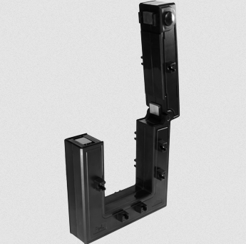
| AcuCT-3135R |
Specifications
Full specs (data-sheet PDF)
- ANSI C12.20 0.5% revenue grade accurate when used with the eGauge Core or Pro meter
- Window size: 80mm (3.15'')
- UL 2808 Listed, 61010-1, and CSA 22.2
- IEC 60044-1 0.5s class
- 333.33 mVrms voltage output at rated full scale current
- 2.4m (8') twisted pair 22 AWG lead with CT connector
- -15 to 65 °C
- 50/60 Hz
- CAT III: 600 Vac
- Pollution Degree 2
- 5-year Limited Warranty
Hardware included
- 1x AcuCT-3135R split-core CT with built-in 8 foot leads and 2-pin plug affixed
- Mounting accessories
- 4x metal surface-mounting tabs
- 5x conductor-mounting set (screw, nut, and plastic standoff)
Assembly/installation information
See the Installation Overview Tips to get started.
-
To reduce risk of electric shock, open or disconnect circuits from the power distribution system (or service) of the building before installing or serving CTs. Ensure any mounting is performed in compliance with all local and national electrical codes.
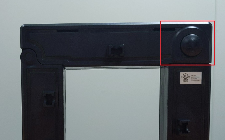
- Open the CT by gently squeezing the latch buttons (circular buttons with an up arrow on the side opposite the hinge, see below for an image). Do not touch the polished ferrite core surfaces. Any oils or debris in that area worsens accuracy.
- Slide the CT over the conductor of the circuit to be measured. Make sure the arrow on the bottom of the CT points in the same direction of the primary current flow (the current flow that should yield a positive power reading).
- Close the CT by gently pushing down on top of the CT until the latch engages. The CT may click twice.
- Verify that the CT is fully closed by squeezing together the top and bottom parts of the CT.
- Optional: secure the CT using the mounting options.
- Route the twisted pair wires of the CT to the meter such that they do not directly contact live terminals or bus bars.
- Plug the 2-pin terminal at the end of the twisted pair wires into an unused port on the meter.
- Configure the sensor input in the meter interface and complete the general configuration.
|
|
| AcuCT-3135R latch button to open CT window, one on each side |
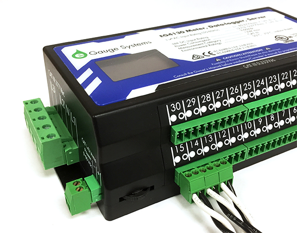 |
| CTs connected to eGauge meter. |
Mounting Options
Do not attempt to use mounting accessories to have the CTs weight held by the conductor being measured. The CT should be resting or mounted directly to a surface.
AcuCT-3135R come with mounting parts that may be used to secure the CT. The original manufacturer's mounting information may be found here.
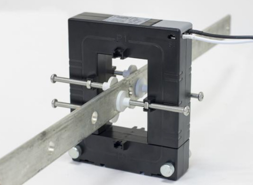
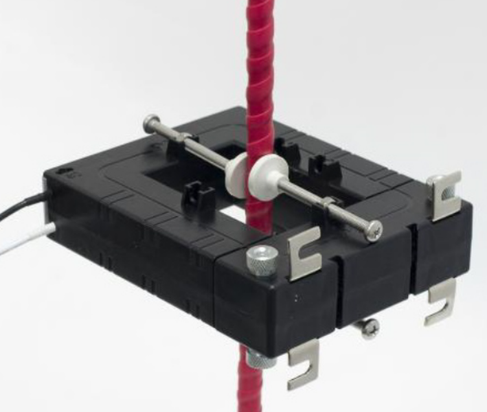
Busbar or Cable:
- Place the screw caps at the end of the screws
- Position the washer on the screw to the desired position on the screw
- Insert washer into the small opening located near the window of the CT so that the screw cap is touching busbar/cable
- Ensure that the screw caps are firmly securing the busbar and cable
For mounting the CT on a surface, the following should be applied:
- Place the mounting clips in the slots located by the removable top portion
- Ensure mounting clips are securely placed in the slots
- Using four screws (not included), place the screws through the mounting clips and tighten to attach to surface
AcuCT-3135R Mounting Options |
Documents
Related Information
- CT Selection Guide
- What CT do I choose from the configuration menu?
- Other supported Current Transformers