
DC (Direct Current) CTs
Visit the online store page
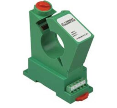
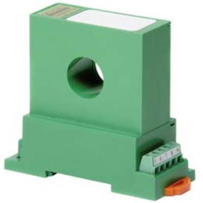
DC CTs measure Direct Current, as opposed to Alternating Current like standard split-core CTs monitor. Direct Current CTs are available in both split-core and solid-core versions. The DC CTs currently offered are Hall Effect style, uni-directional and require a 12Vdc power supply and special leads provided by eGauge. For pricing and available models, see the online store.
Please see the wiring information sheet before installing. Use of special leads (provided) are required for use with the eGauge. Damage may occur if installed without leads or improperly.
|
|
|
| Split-core DC CT | Solid-core DC CT |
Specifications
Full specs (data-sheet PDF)
- Basic Accuracy: 1.0 %
- Linearity: 10% to 100% FS
- Thermal Drift: 500 PPM/°C
- Operating Temperature: 0°C to +50°C
- Installation Category: CAT II
- Isolation Voltage: 3500KVRMS/1mA/1Sec
- Response Time: 250 ms
- Insulation Voltage: 2500 VDC
- Supply Voltage: 12 VDC ±10%
- Weight: 0.5 lbs.
Hardware included
- 1x 12V DC CT
- 1x 8' twisted pair leads w/ resistor and 2-pin plug affixed
- 1x 12Vdc power supply
Assembly/installation information
See the Installation Overview Tips to get started.
The DC CT outputs 4-20mA and requires special leads to convert the signal. Damage may occur if installed without leads or improperly.
- The manufacturer offers both 12Vdc and 24Vdc versions; eGauge supplies the 12Vdc version.
- The direction of current matters; the DC CT will read up to 100% of the current rating if current flows in the "X" and out the "O" side; reversing this will cause the DC CT to read at maximum 20% of the current rating.
-
To reduce risk of electric shock, open or disconnect circuits from the power distribution system (or service) of the building before installing or serving CTs.
- If using a split-core CT, twist the orange knob to open the CT and gently pull the ends apart. Do not touch the polished ferrite core surfaces. Any oils or debris in that area worsens accuracy.
- Slide the CT around the conductor of the circuit to be measured. Make sure the primary current flow direction enters the side marked "X" and out of the side marked "O".
- If using a split-core CT, close the CT by gently pushing the ends of the CT together and twisting the knob back to the locked position.
- Verify that the CT is fully closed.
- Optional: secure the CT to the conductor with a cable tie.
- Wire the power supply and output leads to the DC CT terminals as described in this document.
- Route the twisted pair wires of the CT to the meter such that they do not directly contact live terminals or bus bars.
- Plug the 2-pin terminal at the end of the twisted pair wires into an unused port on the meter.
- Configure the sensor input in the meter interface and complete the general configuration.
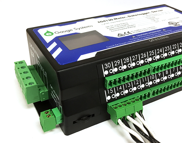 |
| CTs connected to eGauge meter. |