Sensor Hub (ESH044)
Visit the online store page
Model: ESH044
For use with supported eGauge sensors.
Only use straight-through RJ-11 cables to connect powered sensors to the Sensor Hub. Telephone systems generally use "reverse" style RJ-11 cables which are incompatible with the Sensor Hub. See this article for more information on verifying the correct RJ-11 wiring. Every Sensor Hub compatible sensor sold by eGauge Systems comes with a straight-through RJ-11 cable.
The eGauge Sensor Hub can connect up to four sensors to EG4xxx meter inputs. Any combination of powered and non-powered sensors can be used. Switches select whether the powered or non-powered port is connected to the meter. The RJ-45 breakout cable is used to connect the Sensor Hub to up to four neighboring inputs on the meter. The RJ45 coupler can be used to extend the length of the RJ45 cable as needed. Multiple Sensor Hubs can be used to connect more than four sensors to a meter.
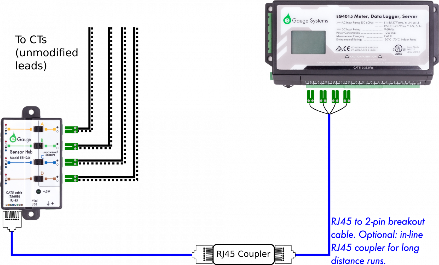
For current transformers (CTs), the Sensor Hub provides a convenient method to extend CT cable length without requiring splicing or modifying the CT leads.
For current transformers (CTs) total combined distance for the RJ45 cable and CT leads must not exceed 100'/33m.
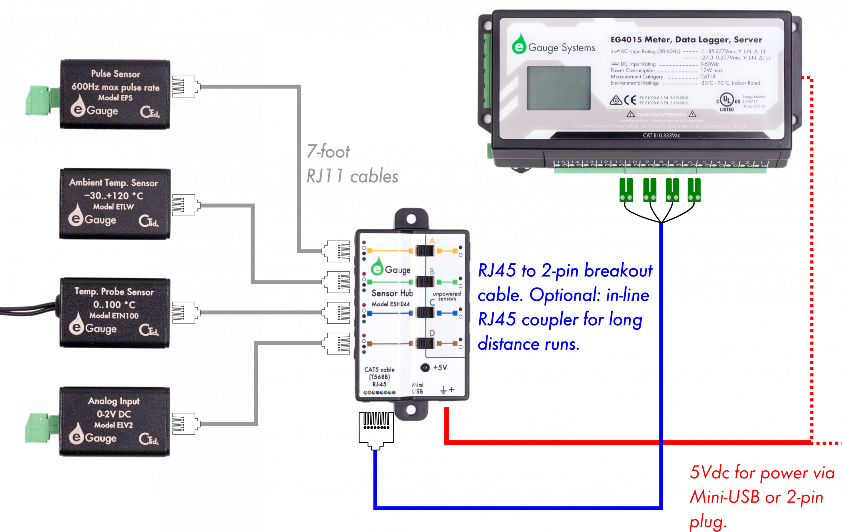
For powered sensors, the Sensor Hub provides a convenient method to adapt from the sensor's RJ11 cable to the 2-pin terminal plug of the EG4xxx meter. The 5V supply required for these sensors can be provided via mini-USB cable or 2-pin terminal plug.
For powered sensors total combined distance for the RJ45 cable and CT leads must not exceed 1650'/500m.
See our Sensors product introduction video here.
|
eGauge Sensor Hub (ESH044) |
Specifications
Full specs (data-sheet PDF)
- ABS
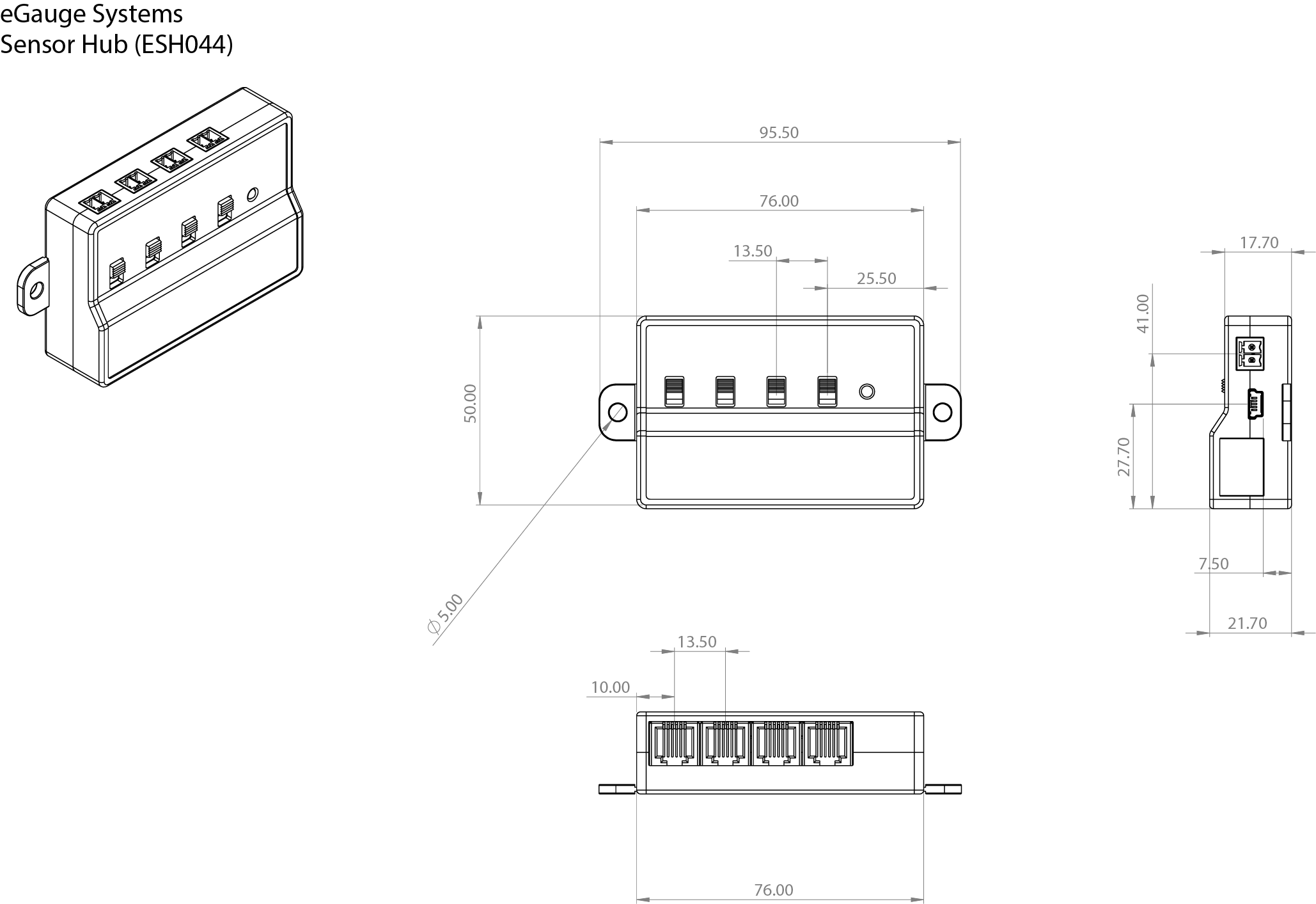
- 75 x 50 x 21 (mm)
- 3 x 1.8 x 0.8 (in.)
- 2 breakway mounting tabs for 5mm fasteners
- 2 DIN rail 3mm coarse thread screw holes, 4mm depth on back (compatible with EG4xxx meter mounting kit)
- -30 °C to 70 °C
- Humidity range: Up to 80%
- 47 CFR Part 15, Subpart B – Unintentional Radiators, Class B for Home or
Commercial use - 2-year limited warranty
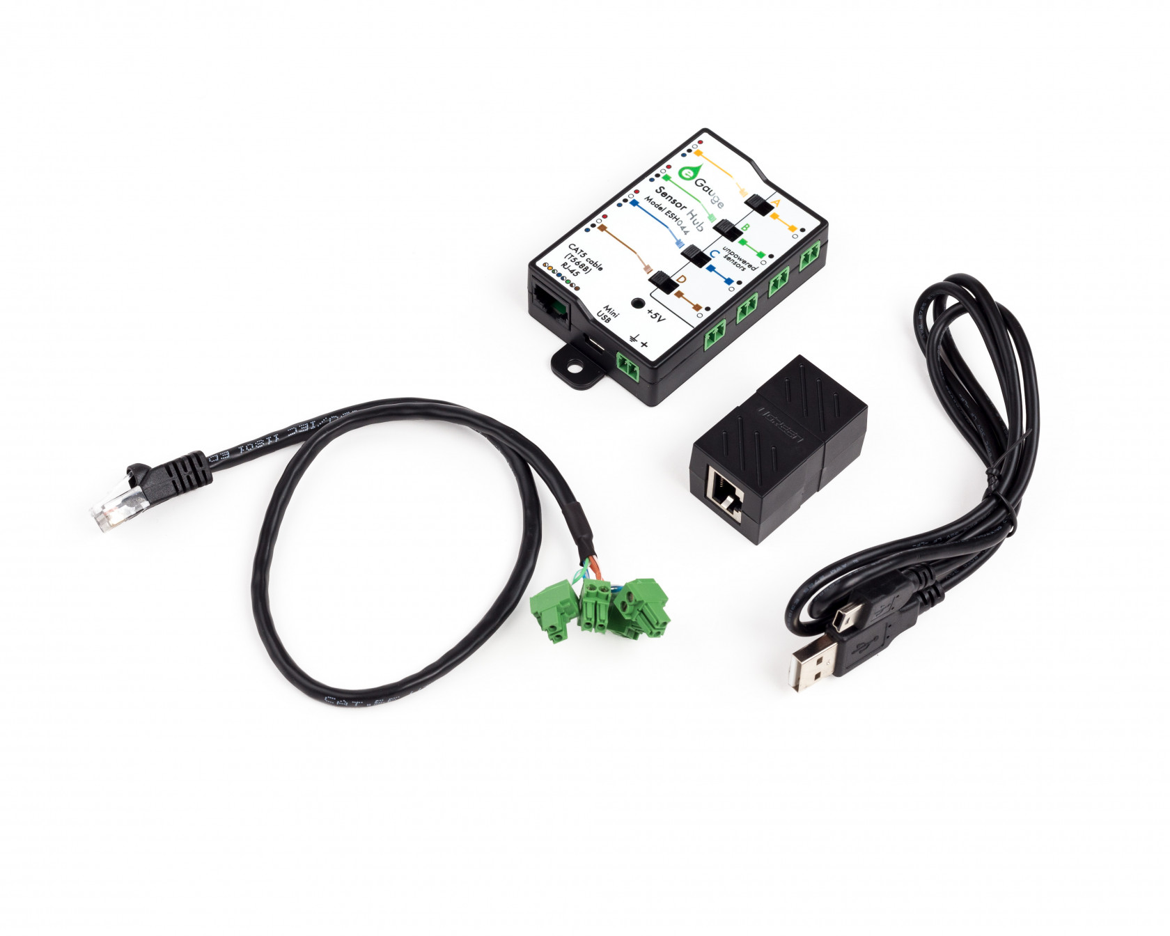
Hardware included
- 1x Sensor Hub
- RJ-45 coupler
- 19" RJ-45 to 2-pin breakout cable
- 3' Mini-USB cable for power
Documents and Related Information
Assembly/installation information
Only input +5Vdc to the power terminal (if not using USB) when using powered sensors (RJ-11 connections). Other voltages will cause damage.
- The switch must be in the correct position (left for RJ11 connected sensors, right for 2-pin sensors)
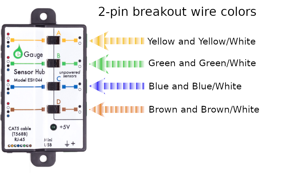
- Lines adjacent to the to the inputs have colors that match the 2-pin breakout cable color pairs
- If extending CTs, do not install the Sensor Hub inside a distribution or breaker panel, only the CTs should be inside.
- Connect the sensor to one of the 4 ports on the Sensor Hub. If using CTid powered sensors such as the ETN100 (temperature probe), ETLW (ambient temperature), EPS (pulse), ELV2 (2V analog / dry contact), or EV1000 (high voltage sensor) the sensors connect via RJ11 on the left-side of the Sensor Hub. If extending CTs, the 2-pin plug on the CT lead connect to the 2-pin sockets on the right-side of the Sensor Hub. A combination of CTs and powered sensors may be used. Only a single powered or unpowered sensor may be used on each port (yellow/A, green/B, blue/D, and brown/D).
- Set each switch to the side the sensor is connected. If a powered sensor is connected to the port adjacent to the yellow line, the adjacent switch should be in the left position.
- If using powered sensors, the Sensor Hub must be powered by 5V DC. This can be either via Mini-USB or the 2-pin plug to the right of the USB port. Using any voltage except 5V DC will cause damage to attached sensors and possibly the eGauge meter. If only using for CT extensions, do not power the Sensor Hub. The LED will turn green when there is power applied.
- If the distance from the Sensor Hub to the eGauge is ~1 foot or less, connect the included RJ45 to 2-pin breakout cable to the RJ45 port to the left of the USB on the Sensor Hub. If there will be distance between the eGauge meter and Sensor Hub
- Run a standard CAT5 Ethernet cable between the eGauge and Sensor Hub location.
- Connect one end of the Ethernet cable to the Sensor Hub RJ45 plug.
- On the other end, attach the RJ45 coupler (included with the Sensor Hub) to the Ethernet line, then connect the Ethernet to 2-pin breakout cable to the other side of the RJ45 coupler.
- Connect the 2-pin plugs of the breakout cable to the eGauge sensor ports. The color of the twisted pair wires on the breakout cable match with the colored lines on the Sensor Hub to identify which sensors they are for. See images below.
- If using a CTid sensor that reads external signals, such as the EC420 or EPS, connect the output of the sensor to the CTid sensor connected to the Sensor Hub. Not all sensors utilize all inputs. Refer to the Assembly/installation information information in the sensor's product page in the support library for specific information.
- Finally, configure the sensors that were connected.
2-bin breakout cable colors
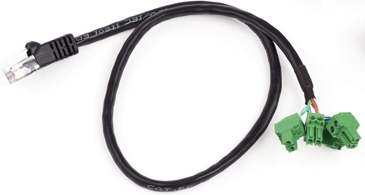 |
| RJ-45 to 2-pin breakout cable. Each 2-pin plug uses either green+green/white, blue+blue/white, brown+brown/white, or yellow+yellow/white. |
Powered Sensor Wiring Diagram
CT Extension Wiring Diagram
