
Remote Devices and Third Party Devices
Overview
The eGauge can record data from a variety of remote devices. This includes other eGauge meters (via UDP over a local network or via TCP through the proxy server) and third party devices via Modbus TCP or Modbus RTU (using a USB to RS485 converter). Third party devices include any piece of standalone hardware not manufactured by eGauge Systems (ie, anything that's not another eGauge meter).
Data read from remote devices can be displayed through the eGauge user interface, allowing multiple relevant data points to be aggregated in a single location. For example, an eGauge could monitor solar production locally using CTs, then pull additional performance data from the inverter and environmental data from an environmental sensor. Data stored in this way uses register slots on the "master" eGauge meter, meaning there is a limit to how much data can be imported into a single eGauge. For information on database capacity, see this article.
Breaks in communication will result in gaps in the historical data imported by the "master" eGauge meter. These gaps cannot be backfilled or adjusted.
Remote devices are configured under Settings -> Installation in the "Remote Devices" section. Best practice is to configure the remote device itself first (eg, ensure the remote device is reporting complete and valid values through that remote device's interface), then configure the "master" eGauge to read data from that remote device.
Table of Contents
Example Remote Device Configuration
Supported Protocol Configuration
Example Remote Device Configuration
The following image shows an eGauge configured to record building consumption using CTs, and recording a solar inverter via Modbus RTU (RS485):
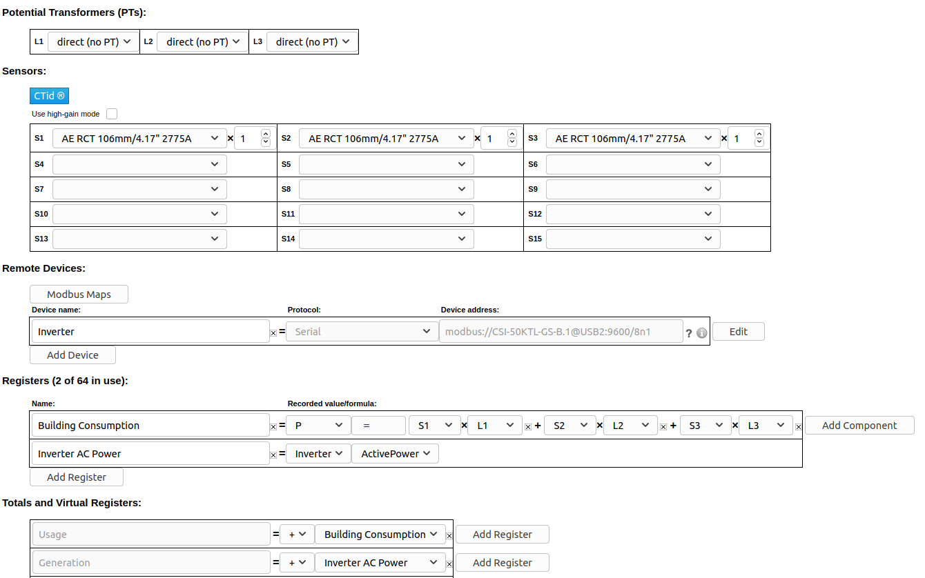
There are 3 fields to configure for a remote device:
Device Name: This name describes the remote device. In the above example, the remote device is a solar inverter and has been named "Inverter". The name is completely arbitrary, but should make sense to the user.
Protocol: The protocol used by the remote device. In the above example, the remote device is using Modbus RTU via an RS485 (serial) connection, and therefore "Serial" is the protocol. A full list of supported protocols is available in the Supported Protocol Configuration section of this document.
Device Address: This describes the remote device and how to communicate with it. The formatting for the device address varies based on the protocol supported by that device, and is explained in detail in the appropriate section for that device:
Remote eGauge Device Address Format
Modbus RTU Device Address Format
Modbus TCP Device Address Format
ControlByWeb Device Address Format
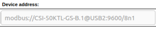
In the example above, the device address specifies the remote device is using Modbus RTU (modbus://), the device map is CSI-50KTL-GS-B, with a unit ID of 1 (.1), is read via a serial to USB adapter on USB port 2 (@USB2), uses 9600 baud, 8 data bits, no parity, and 1 stop bit (:9600/8n1).
Verifying A Remote Device
After a remote device is configured, the remote device must be verified. To do this, click the grey "?" question mark to the right of the device address field. This will attempt to resolve and read data from the remote device. If this succeeds, the question mark will turn into a green check-mark, indicating the remote device is reachable and returning data.
The remote device will need to be re-verified every time the Installation page is reloaded.
Reading From A Remote Device
To actually record data from a remote device, it must first be verified using the process above. Assuming that is successful, create a new register in the "Registers" section by clicking the "Add Register" button. Select a name for the new register. Using the dropdown menu, change the default "P" to the remote device name. A second dropdown menu will appear - select the appropriate register from the list. Make sure to click "Save" at the bottom of the page to save these changes.
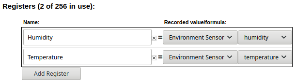
In the example above, the eGauge is set to record two registers from the remote device "Environment Sensor".
Supported Protocol Configuration
Some protocols are deprecated or unsupported and are not documented here.
Remote eGauge via UDP/TCP
These protocols are used to have a master eGauge meter read from a secondary eGauge meter. There are two options available - UDP or TCP. This can be used at installations where multiple eGauge meters are present to allow the end user to see a single consolidated view instead of navigating to multiple meters. This protocol is only supported by eGauge meters, and cannot be used with third party devices.
Remote eGauge Device Address Format
UDP is generally the more stable and reliable option, but only works over local networks where UDP access is available. The Device Address string is simply the device name of the remote eGauge. An IP address can also be used, but the meter should either be set to use a static IP address or assigned a DHCP lease reservation.
TCP uses a connection over TCP port 80 instead of UDP. The Device Address can be a device name, IP, or FQDN (do not specify "http://" or use any slashes in the address). A TCP connection can be established over the eGauge proxy server, meaning it's possible to pull data from meters at multiple sites into a single master eGauge. However, this connection may be unstable.
Remote devices with site-wide password protection will not allow for remote eGauge via TCP to be used.
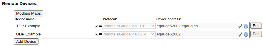
The example below shows a master meter configured to read from "eGauge52002" via both UDP and TCP.
Serial
This protocol is used for devices being read over a serial line. This includes Modbus RTU (both SunSpec and non-SunSpec), SMA and Power-One via serial. Serial data can be read over a local USB port on the EG4xxx using a USB to RS485 converter, or on the EG30xx and EG4xxx meters using RS485 to Ethernet converter over a local network (LAN).
Modbus RTU Serial Protocol
The device address for serial devices is as follows:
modbus://DEVTYPE.SERIAL_ADDR@CONV_ADDR:PARAMETERS
where:
DEVTYPE is the device type. This can be the name of a Modbus map. See this article for information on how to find and create Modbus maps.
SERIAL_ADDR is the serial address (also referred to as the slave address, device ID, or unit ID) of the remote device.
CONV_ADDR is the address of the serial converter. For USB-serial converters, this can be USB1 or USB2 (case-sensitive). If using a serial-to-Ethernet converter, this can be the hostname, MAC address, or IP address of the converter.
:PARAMETERS are additional addressing parameters which may be specified.
If using a USB485 converter, the format is :BAUD/[DATA_BITS][PARITY][STOP_BITS]. BAUD is the baud, DATABITS is the number of data bits, PARITY is n for "none", e for "even" or o for "odd", and STOP_BITS are the number of stop bits. Examples include :9600/8n1 and :19200/8e1. It is most typical to have 8 data bits, no parity, and 1 stop bit. If the Modbus map defines default serial parameters, this may be excluded.
If using an Ethernet-serial converter, :PARAMETERS specifies a TCP port. If omitted, the eGauge defaults to use port 50,000 which is the default for the support BF-430 converter.
Examples
modbus://imt_si.1@USB1
modbus://cps403x.5@USB2:9600/8n1
modbus://ae75_100tx.1@192.168.1.241 Note this is using an IP address to specify a serial-Ethernet converter like the BF-430.
SMA Serial Protocol
Legacy SMA serial devices may be configured in the format of:
sma://@CONV_ADDR
where:
CONV_ADDR is the address of the serial converter. For USB-serial converters, this can be USB1 or USB2 (case-sensitive). If using a serial-to-Ethernet converter, this can be the hostname, MAC address, or IP address of the converter.
Example
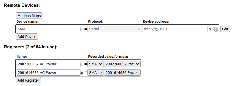
Note: The SMA serial protocol self-defines register names and are prefixed by the serial number of the device being read from. In the above example, "Pac" is the AC Power for the prefixed serial number.
Power-One Aurora Serial Protocol
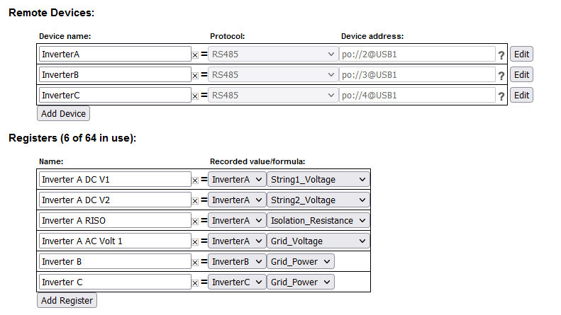
Legacy Power-One Aurora serial devices may be configured in the format of:
po://UNIT_ID@CONV_ADDR
where:
UNIT_ID is an optional ID of the inverter being read from. This may be omitted to perform auto-discovery. If auto-discovery fails, please specify the UNIT_ID in a separate remote device address for each inverter on the serial chain.
CONV_ADDR is the address of the serial converter. For USB-serial converters, this can be USB1 or USB2 (case-sensitive). If using a serial-to-Ethernet converter, this can be the hostname, MAC address, or IP address of the converter.
Example
Modbus TCP
Modbus TCP is a protocol that operates over a local TCP/IP network. The remote device must be connected to the same local network as the eGauge.
Using Modbus TCP over the internet (across networks) is unsafe and not supported.
Modbus TCP Device Address Format
The device address format for Modbus TCP is as follows:
DEVTYPE.UNIT_ID@ADDR:TCP_PORT
where:
DEVTYPE is the name of a Modbus map. See this article for information on how to find and create Modbus maps.
.UNIT_ID is the unit ID (also referred to as slave address or device ID) of the Modbus device. If omitted, this defaults to 255. Some Modbus TCP devices do not care what unit ID is specified.
ADDR is the address of the Modbus device. This may be an IP, hostname, or FQDN.
:TCP_PORT is optional to specify a non-default Modbus TCP port. If omitted, this defaults to the standard Modbus TCP port of 502.
Examples
ControlByWeb
The eGauge can read from many ControlByWeb products that are network-enabled. This includes the X-320, X-410, X-420 and others. These ControlByWeb devices run a local webserver which the eGauge can read from over the local network. Communication is handled through HTTP requests, meaning only local communication (over the same network) is supported.
ControlByWeb Device address format
The format for the remote device is simply the IP address of the ControlByWeb device. The ControlByWeb hardware must have a static IP configured or DHCP reservation on the network so the IP address doesn't change unexpectedly.

The following data points are supported. Note that X indicates a there may be multiple data points of that type available (this depends on the model). For example, "countX" could be "count1", "count2", and so on.
frequency (frequency input)
vin (voltage powering the CBW device)
countX (pulse reading)
analogInputX (analog input value)
oneWireSensorX (one wire temperature sensors)
sensorXtemp (temperature sensors)
extvarX (external variable)
digitalIOX (binary digital IO value)
Although the eGauge can read from ControlByWeb devices, CBW hardware is not officially supported by eGauge Systems. For configuration questions on the CBW hardware itself, contact ControlByWeb directly.
For questions regarding whether a specific ControlByWeb model is compatible with the eGauge, contact eGauge support directly.