Modbus Control of PRM3
Back to Main Power Relay Module (PRM3) Product Page.
The Power Relay Module acts as a Modbus server. As such, it responds to requests sent by a client. It never initiates a request on its own.
Connection and Power
Power
The eGauge PRM3 may be powered using the USB-A or the 4-pin port with a 5V/500mA power supply. Only power the PRM3 with one of these methods.
Communication
The PRM3 uses the 4-pin port for Modbus RTU RS-485 serial communication.
Modbus Registers
All registers are holding registers. They can be read with "Read Holding Registers" (function code 0x03) and written with "Write Single Register" (function code 0x06). The PRM3 uses base-0 addressing.
| Address |
Size |
Name |
Type |
Description |
| 0 |
1 |
RS-485 param |
Unsigned 16-bit integer |
Baud Rate code (bits 0..7) and parity (bits 8..15)* |
| 1 |
1 |
Unit number |
Unsigned 16-bit integer | Modbus unit number (1–247) |
| 2 |
1 |
Relay Mask |
Unsigned 16-bit integer |
Relay status. On write, if bit (n-1) is set, relay n is closed, opened otherwise. On read, if bit (n-1) is set, relay n is closed, open otherwise. |
| 3 |
1 |
Relay Set |
Unsigned 16-bit integer | Close relays. On write, if bit (n-1) is set, relay n will be closed, unchanged otherwise. On read, if bit (n-1) is set, relay n is closed, open otherwise. |
| 4 | 1 |
Relay Clear |
Unsigned 16-bit integer |
Open relays. On write, if bit (n-1) is set, relay n will be opened, unchanged otherwise. On read, if bit (n-1) is set, relay n is closed, open otherwise. |
| 100 |
2 |
EEPROM writes |
Unsigned 32-bit integer |
Number of times EEPROM has been written. |
| 102 |
2 |
Relay 1 Count |
Unsigned 32-bit integer | Relay 1 switch count. |
| 104 |
2 |
Relay 2 Count |
Unsigned 32-bit integer | Relay 2 switch count. |
| 106 |
2 |
Relay 3 Count |
Unsigned 32-bit integer | Relay 3 switch count. |
| 108 |
1 |
Min. open duration |
Unsigned 16-bit integer |
Minimum duration (in seconds) for which a relay stays open. |
| 109 |
1 |
Min. close duration |
Unsigned 16-bit integer | Minimum duration (in seconds) for which a relay stays closed. |
RS-485 parameter register*
The “RS-485 param” register provides access to the RS-485 baud rate and parity.
The upper eight bits define the parity as shown below. Note the numerical value is the decimal value of the ASCII code, not a binary value.
| ASCII code |
Value (decimal) |
Parity Mode |
| n |
110 |
no parity |
| e |
101 |
even parity |
| o |
111 |
odd parity |
The lower eight bits define the baud rate as shown below:
| Value (decimal) |
Baud Rate |
| 1 |
9600 bps |
| 2 |
19200 bps |
| 4 |
38400 bps |
| 6 |
57600 bps |
| 12 |
115200 bps |
For example, a value of 0x6506 would indicate 57600 bps and even parity.
Unit Number
The “Unit number” register defines the Modbus unit number under which the device responds. By default, this value is 1 but it can be set to any number in the range from 1 to 247.
Relay Commands
For more information about using masks to control relays see this article.
The “Relay mask", “Relay set", and “Relay clear" registers provide access to the relays.
They all return the same value when read: in the returned value, if bit (n − 1) is set, it means that relay n is closed and if it is cleared, it means that the relay is open.
When written, the three registers have different behavior: “Relay mask" sets all the relays as indicated by the written value. That is, if bit (n − 1) is set, relay n will be closed and otherwise it will be opened. In contrast, writing “Relay set" will only close the relays for which the corresponding bit is set. Similarly, writing “Relay clear” will only open the relays for which the corresponding bit is set.
SunSpec block
The Power Relay Module also provides an address block to enable device identification according to the SunSpec standard.
Since SunSpec does not have a standardized model for relay controllers, the only model block provided is the Common Model (SunSpec DID 0x0001) as shown below. This block allows identifying the device by manufacturer and model name.
| Address |
Size |
Name |
Type |
Description |
| 40000 |
2 |
SunSpec_ID |
Unsigned 32-bit integer |
Value = 0x53756e53 ("SunS”). |
| 40002 |
1 |
SunSpec_DID |
Unsigned 16-bit integer |
Value = 0x0001 (Common Model Block) |
| 40003 |
1 |
SunSpec_Length |
Unsigned 16-bit integer |
Value = 65 (Length of block). |
| 40004 |
16 |
Manufacturer |
32-bit string |
Manufacturer "eGauge". |
| 40020 |
16 |
Model |
32-bit string |
Model name (e.g., “PRM3"). |
| 40036 |
8 |
Options |
16-bit string |
Installed options. |
| 40044 |
8 |
Version |
16-bit string |
Product version (e.g., "1.00"). |
| 40052 |
16 |
SerialNumber |
32-bit string |
Serial number (e.g., "3N013453”). |
| 40068 |
1 |
DeviceAddress |
Unsigned 16-bit integer |
Modbus unit number. |
| 40069 |
1 |
SunSpec_DID |
Unsigned 16-bit integer |
Value = 0xffff (End Marker). |
| 40070 |
1 |
SunSpec_Length |
Unsigned 16-bit integer |
Value = 0x0000. |
Accessing the PRM3 from a Windows PC
eGauge Systems does not test or guarantee safety or accuracy of third party software.
Locate the COM port of the PRM3
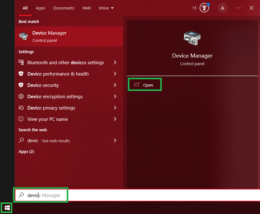
- Open the Device Manager, which can be done by opening the Start Menu and typing "Device Manager" and clicking "Open":

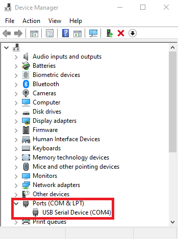
- Expand the "Ports (COM & LPT)" section:

If you have multiple "USB Serial Device" entries, you may unplug the eGauge PRM3, and plug it back in to see which COM port appears when it is connected.
Using QModMaster to communicate with relay
- Install and open the QModMaster Modbus master simulator.
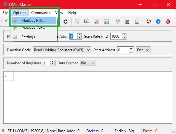
- Click Options and "Modbus RTU..." to configure the Modbus connection

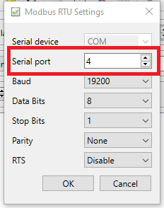
- Change the COM port number and other parameters if necessary and press OK. The defaults RS-485 settings for the eGauge PRM 3 are 19200 baud, 8 data bits, 1 stop bit, no parity:

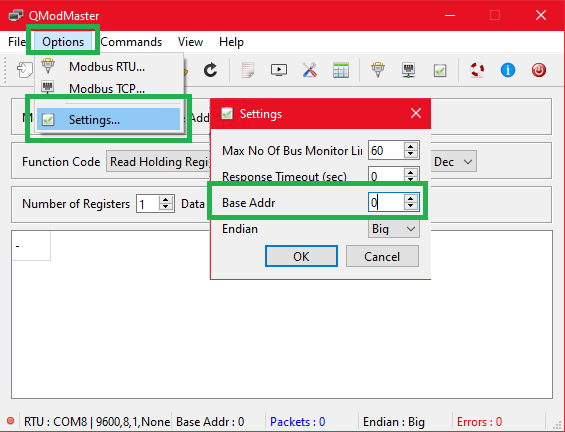
- Open the Options menu again and go to Settings, and change Base Addr to the number 0:
Using an incorrect "Base Address" will result in reading or writing to a register one address lower or higher than the intended register address!
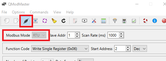
- Ensure Modbus Mode is set to RTU and click the "connect" button in the toolbar below the "Options" and "Commands" menus:

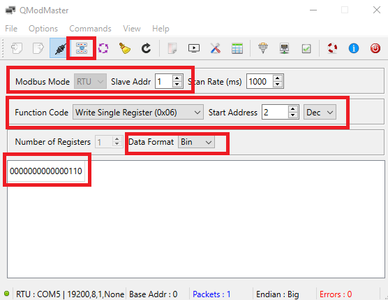
- First, we will set the mask of the relay to 6 (110) to open relay 1, and close relays 2 and 3.
- Ensure the Slave Address (Unit Number) is set correctly. The PRM3 by default is set to 1
- Choose "Write Single Register (0x06)"
- Set Start Address 2 (decimal format)
- Choose "Bin" (binary) for Data Format, this is easier to work with masks
- In the box enter "110" and click outside the number entry box to save it there
- Click the "Read/Write" button next to the connect button
After sending, the "Packets" (blue text at bottom) number should increment.

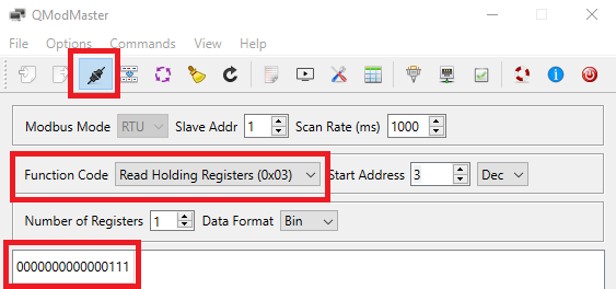
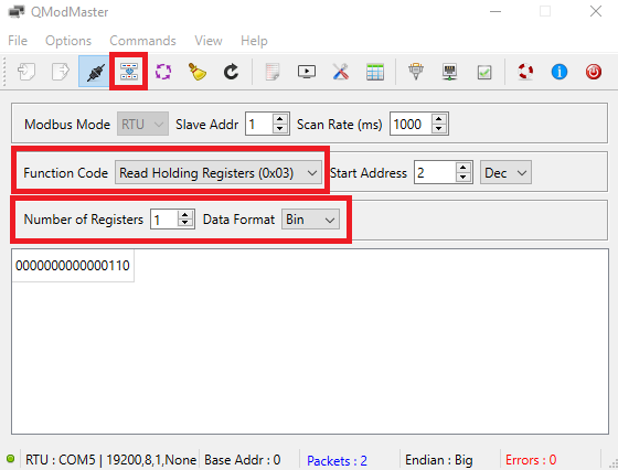
- Read back the register to confirm the mask was set. Change Function Code to "Read Holding Registers (0x03)", and ensure "Number of Registers" is set to 1 (as it is a 16-bit value) and Data Format as "Bin". Click the Read/Write button again and the Packets should increment. The box should still show "110", meaning relay 1 is open, and relays 2 and 3 are closed.
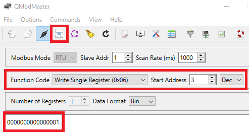
- Let's turn relay 1 on and leave 2 and 3 alone, we will use the "Relay Set" register for this (address 3). Change the "Start Address" to 3, the Function Code back to Write Single Register, and the 110 in the text box to 001 (leading zeros are not necessary). This tells the PRM3 to close relay 1, and leave 2 and 3 in their current state. Press Read/Write and note the packet increment:
- Finally, we'll read current the mask state of the relay. Change the Function Code to Read Holding Registers and click the Read/Write button. We can read from any of the Relay registers to get the current mask from the relay. Note the packet increase. The text area below shows the data received, which is 111 to indicate all 3 relays are closed.