Monitoring High Voltage DC Loads
Overview
The EG4xxx meter features a low voltage terminal (Ldc) which can be used to measure 9-60Vdc (12-60Vdc is required to power the meter from the Ldc terminal). However, there are many monitoring applications where DC voltage exceeds 60Vdc. String-based inverter monitoring is probably the most common application. It's also common to have multiple DC voltage references, but the Ldc terminal can only support one measurement.
Using several EV1000 High Voltage Sensors and an ESH044 Sensor Hub, it's possible to measure higher DC voltages directly (up to 1000Vdc). This can be used anywhere there are multiple DC voltage measurements. Note that each EV1000 sensor uses a sensor port on the eGauge, so a single EG4xxx meter can support either 15 or 30 high voltage sensors (depending on meter model). As CTs also use sensor ports, the number of high voltage sensors used will likely be lower (so CTs can also be used).
This guide only applies to EG4xxx meters. Older EG30xx and eGauge2 meters do not support the EV1000 or CTid CTs.
Installation Considerations
There are a few general concerns when using EV1000 high voltage sensors:
1. EV1000 sensors must be connected directly to the DC voltage source. Make sure to follow all necessary safety precautions and code requirements for your area.
2. Sensor Hubs must be powered. Up to 2 hubs can be powered directly from the eGauge via the USB ports on the meter. For installations where more hubs are required or the USB ports are in use (e.g., for Modbus RTU communication) the hubs can be powered directly from a 5Vdc power supply.
3. All hardware must be installed in a suitably rated enclosure. eGauge Systems offers several powered enclosure kits which are suitable for this purpose. Most kits feature DIN rails (for mounting the eGauge meter and EV1000s securely) along with a powered receptacle and optional stepdown transformer (which can be used to power the 5Vdc supply for the sensor hubs and/or other supporting hardware).
Examples
The following are general examples which may be useful for planning a specific installation. Note that these examples may omit certain details (for example, not all ports are shown on the eGauge meter). These are intended to serve as guidelines only - always consult local code requirements when planning an installation.
Hardware appearance in the following diagrams may not reflect the actual size or layout of actual hardware. Refer to the product pages for actual measurements.
Configuration examples are correct for the diagram shown. Actual installations will likely use a different combination of ports, different CT types, and so on.
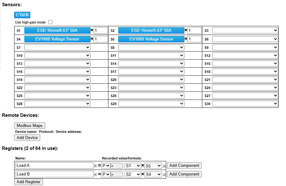
Monitoring multiple DC loads
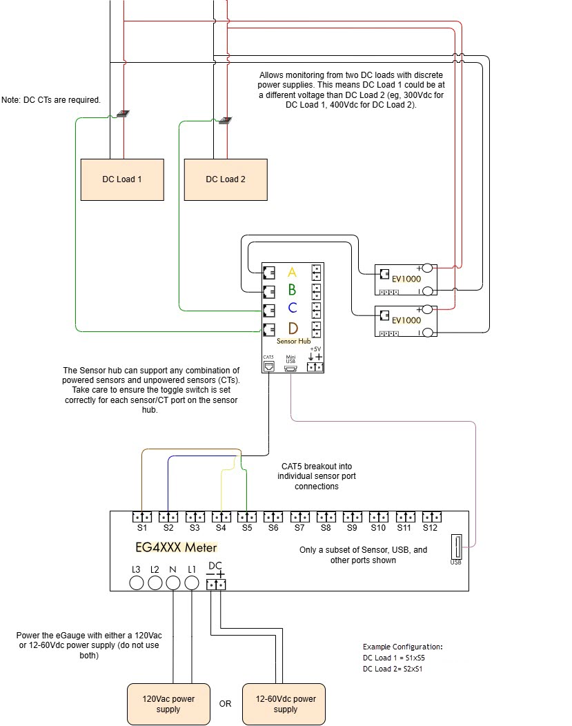
The meter configuration would be set as follows below. Your DC CTs may scan with different information depending on the model. For more information on CTid please see: Configuring CTid Sensors.