
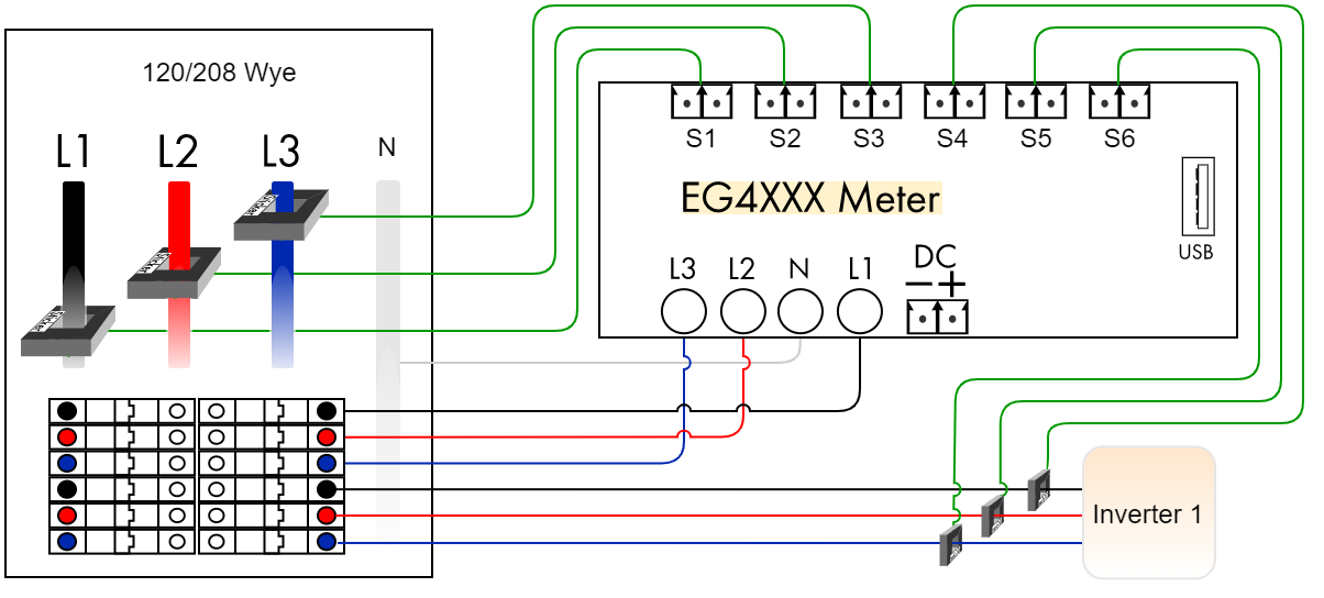
3-Phase Inverter
Standard three-phase installation measuring power coming from a power utility (grid) and from a three phase solar-system inverter. The color coding shows 120/208V, but applies to 277/480V as well. This diagram is for a Wye system with a neutral. Refer to delta diagrams for systems without neutral.
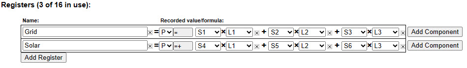
Registers
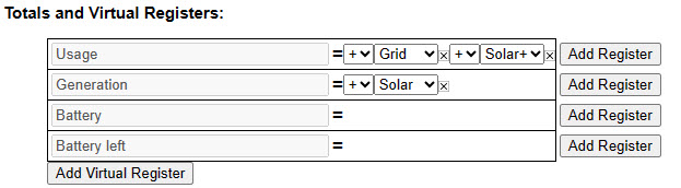
Totals and Virtual Registers
Notes
- Three-phase installations are set up the same as split-phase systems, except that a third voltage-tap
(L3) and a third Grid CT is required to measure power flow on phase 3. - Three-phase inverters require a CT on each phase. Sometimes during low production they will not
output evenly on all 3 legs, and during standby they do not often draw the same amount of current on
each leg. Further, in standby, they may output power on certain legs and draw power on others, which
can lead to seeing erroneous overnight generation if a single CT is used. - If the solar is a line-side tap rather than back-fed, the Usage register should use Solar- rather than
Solar+. See configuration example 3.2, Direct-Feed Solar, for more information.