Visit the online store page
Model: IR302

Info
- Modems sold by eGauge systems are pre-configured for the T-Mobile service provided by eGauge and utilize InHand Networks device manager for remote troubleshooting and customer assistance. This item does not come with a data plan, one must be purchased separately.
Inhand Networks IR302 is a cellular to Ethernet modem that can provide the eGauge unit and related supported equipment with internet access on a 4G LTE T-Mobile network. Use the guidance in this article to install and use your InHand IR302 cell modem.
Prerequisites
- Before installing be sure to activate your data plan by following the instructions included in the box. For more details regarding the activation and management of eGauge-sold data plans please see: Dataplans
Instructions
Before beginning check that you have all of the included parts:
- Inhand Networks IR302 box kit:
| Qty | Item |
| 1 | IR302 Modem |
| 1 | DIN rail clip |
| 1 | AC Power adapter |
| 1 | CAT5 cable |
- eGauge Cellular modem accessory kit:
| Qty | Item |
| 2 | rubber O-ring |
| 2 | Antenna extension cables (short, SMA) |
| 2 | Rubber stick antennas |
The cellular antennas must be located on the outside of any enclosure. Even plastic enclosures can degrade or block a cellular signal.
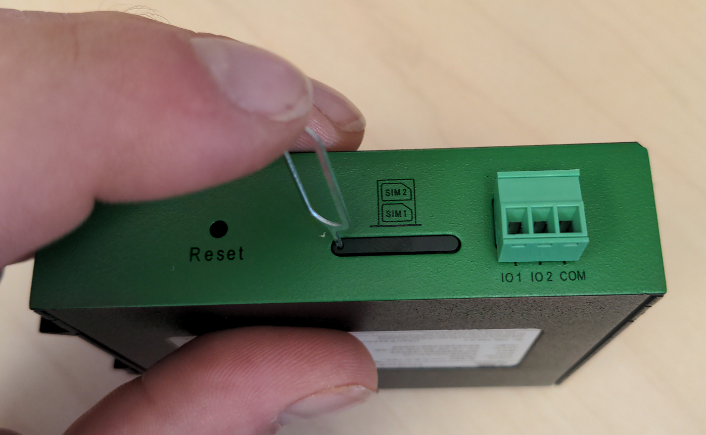
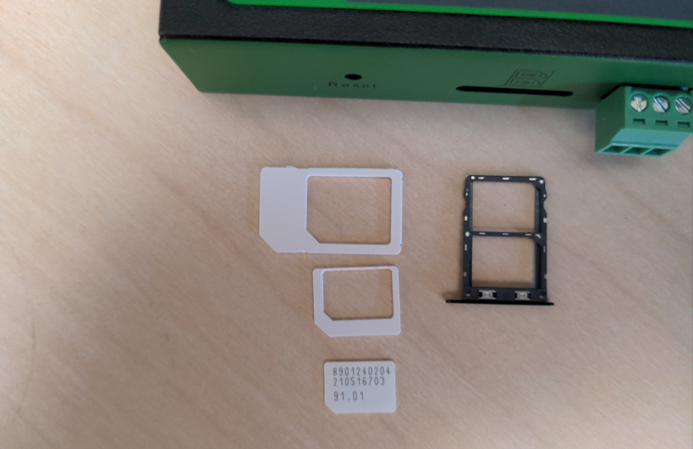
Step 1: If the modem is ordered with a data plan, an activation instruction sheet will be included with a SIM card. Insert the SIM card into the modem as shown below, ensuring the SIM card is in the "SIM 1" position. Follow the data plan activation instructions provided to activate the data plan or see this article for more information if you lost your paperwork.

Detailed SIM card Install instructions
Step 1: Use the SIM card remover tool to eject the SIM card tray.


Step 2: Remove the SIM card from the SIM card holder. The SIM card has 2 outer shells that must be removed prior to inserting into the holder.


Step 3: Insert the SIM card (with no outer shells) into the lower (SIM 1) position of the SIM card holder tray and insert back into the IR302 modem.

|

|
Step 4: Insert the SIM card (with no outer shells) into the lower (SIM 1) position of the SIM card holder tray and insert back into the IR302 modem.

Step 2: Connect the DIN rail to either the left or right side of the modem using the included bracket and screws.
Step 3: Locate a suitable location to install the cell modem. If installing in a Powered Enclosure Kit (PEK), mount on the DIN rail.
Step 4: If using the PEK or other suitable enclosure, use the 2x short SMA extension cables to connect from the Cellular1 and Cellular2 connectors on the modem to create a bulkhead connector on the enclosure.
Step 5: Connect the antennas to the bulkhead connectors on the enclosure, or directly to the cell modem if not using an enclosure.
Step 6: Connect the power included cord to the marked DC voltage port on the front of the cellular modem. The IR302 can accept between 9 - 36 Vdc. This can be provided from a standard electrical outlet using the included power cord or from another DC source of appropriate voltage.
Step 7: Connect the eGauge meter via Ethernet to a LAN port on the modem.
Troubleshooting and Tips
The modem has a "Signal" LED with 3 different colors to indicate the signal strength level:
- Red: Signal strength 0-10 (Signal strength is weak, please check antenna and the signal strength of current location).
- Yellow: Signal strength 11-20 (signal strength is adequate, and the modem can be used).
- Green: Signal strength 21-30 (signal strong).
Other LED behavior is described below:
| Power (red) | Status (green) | Cellular (yellow) | Description |
| Off | Off | Off | Powered off |
| On | Off | Off | System failure |
| On | On | Off | The module or SIM card is not recognized |
| On | On | Blinking | Dialing (Connection attempt is being made) |
| On | On | On | Dialing Succeeded (A connection to the provider was made. This does not guarantee the SIM card data plan is active) |
| On | Blinking | On | Software Upgrade in progress |
| On | Blinking, then On | Off | A reset is being performed |
Additional Diagnostics & Troubleshooting
This section contains information and diagnostics that can be helpful in identifying poor signal or other issues. Connect a computer to a LAN port of the modem and visit http://192.168.2.1/ logging in with username adm and password 123456. If this does not work, perform a factory reset and initial configuration as described in the above sections.
| Page Location | Description |
| Tools → Ping | Have the modem ping an external IP or domain. |
| Status → Modem | Contains signal level, RSSI, SIM card number, network type and other modem-related information |
| Status → Network Connections | Dialup (cellular) IP information from cellular provider |
| Status → Device List | DHCP list of connected devices to the LAN ports |
| Status → Log | Raw log from modem |
Status → Modem Value Descriptions
The following values may be found in Status → Modem.
- RSRP (Reference Signal Received Power) is a measure of of the received power
- RSRQ (Reference Signal Received Quality) is a measure of the quality of the received signal
- SINR (Signal to Interference and Noise Ratio) is another measure of of the quality of the received signal, taking into account the amount of valid data compared to noise or errors received
The table below describes the values for each of the points. If any values are Weak or Medium, modem connectivity may not work or may be intermittent. Conversely, cellular connectivity can be limited or nonfunctional even if all values are Good or Excellent due to issues such as congestion or high traffic on local towers or the providers network, or inter-cell interference.
| Condition | RSRP (dBm) | RSRQ (dB) | SINR (dB) |
| Excellent ✓✓✓ | >=-80 | >=-10 | >=20 |
| Good ✓✓ | -80 to -90 | -10 to -15 | 13 to 20 |
| Medium ✓ | -90 to -100 | -15 to -20 | 0 to 13 |
| Weak | <=-100 | <-20 | <=0 |
Additional Resources
Related Articles