| Model | Orientation |
| J&D (JSxxxx models) | Point the sticker towards what is being measured |
| Orange Rope CTs | Point the arrow towards what is being measured |
| eGauge ECS20 CTs | Current should flow in the same direction the arrow points |
Some CTs require two clicks to close fully.
**Network**: [Visit this KB article](https://kb.egauge.net/books/egauge-meter-configuration/page/accessing-egauge-interface "Accessing eGauge Interface") for how to confirm network connections are up and device interface can be accessed.eGauge support cannot provide the password currently set on a meter or the default password on meters shipped on or after Jan 2021.
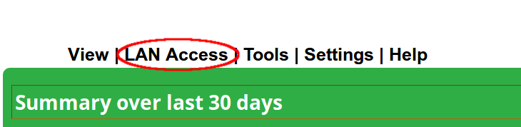
NOTE: If an error stating you are unauthorized to change settings, [enable remote administration](https://kb.egauge.net/books/egauge-meter-configuration/page/register-a-device-remote-access-and-password-resets "Register a device, remote access, and password resets") or click **LAN Access** in the top right corner of the page and try again.Meters sold after June 1, 2023 may default to the [Modern User Interface](https://kb.egauge.net/books/egauge-meter-ui/page/modern-user-interface). After logging into the eGauge meter, choose **Setup >> Other Settings** from the main menu to access the configuration settings and continue as outlined below.
To configure the eGauge, log on to it ([see this KB article](https://kb.egauge.net/books/egauge-meter-configuration/page/accessing-egauge-interface "Accessing eGauge Interface")) and navigate to Settings -> Installation.   --- The full configuration guide can be accessed at [egauge.net/help/config.](http://egauge.net/help/config) Line diagrams with example configurations can be found in Section 2 Configuration Examples, starting on page 13 (as of time of writing this article). Potential Transformers  If step-down transformers are used, select the appropriate transformer ratio or type here. E.g., 480:120 for a generic 480V to 120V transformer, or FDT-480-120 for the Functional Devices transformer provided by eGauge Systems. If eGauge is connected directly to the systems voltage, leave this as "direct (no PT)" ## Sensors/CTs *Note: in firmware v4.0 and greater, "CT" has been changed to "S" for Sensor. For example, CT5 = S5, and CT12 = S12*. The current transformers in each slot are selected here. [See this KB article](https://kb.egauge.net/books/configuration/page/what-ct-do-i-choose-from-the-ct-drop-down-selection) for how to understand the drop-down menu options ## Remote Devices  This can be left alone if no remote devices are used. ## Registers *Note: in firmware v4.0 and greater, "CT" has been changed to "S" for Sensor. For example, CT5 = S5, and CT12 = S12*. Registers can be deleted by clicking the \[x\] to the right of the register name. For each measurement, add a register. Click "Add Component" to add a CTxLine combination. This example shows three-phase Grid being monitored by CT1, CT2, and CT3. Solar 1 is monitored by CT4 and CT5, and is feeding on L1 and L2. Solar 2 is monitored by CT6 and CT7, feeding on L3 and L1. It is vital for CTxLine combinations to be correct. Visit [this KB article](https://kb.egauge.net/books/egauge-installation/page/panel-phasing-and-egauge-installation "Panel phasing and eGauge installation") on information on phase checking with a volt-meter. #### DC load monitoring If monitoring DC loads using the Ldc voltage input, choose "Ldc" instead of L1, L2 or L3. If monitoring DC loads using an [EV1000 voltage sensor](https://kb.egauge.net/egauge.net/support/m/ev1000), choose the appropriate sensor input (e.g., "S4") instead of Ldc or a line input. ## Total and Virtual Registers  The Usage and Generation totaling registers determine the red and green areas on the main graph, as well as summary information for Usage and Generation. For Usage in a back-fed system, positive values of Solar (e.g., Solar 1+ ) are added to Grid. In a line-side feed, the negative values would be added to Usage (e.g., Solar 1- ). Generation consists of all Generating loads. # eGauge Configuration Guide The eGauge is a powerful, highly accurate piece of monitoring hardware. However, it is essential to configure the eGauge properly, or the readings obtained will not be correct. Even on **identical** installations the exact settings may vary, depending on how the eGauge and CTs are installed. The document below covers the various aspects of basic eGauge configuration (assuming monitoring is done exclusively with CTs and voltage taps - [remote devices](https://kb.egauge.net/books/egauge-meter-communication/page/configuring-a-remote-egauge "Configuring a remote eGauge") are only briefly covered in this document). Technical support is available to assist with configuration, but there is no guarantee the device configuration will be set correctly. Ensuring a device is correctly configured falls on the owner or installer of that device. To determine your firmware version, visit **View -> Status** in the device interface. [Configuration Guide for firmware v4.x](https://www.egauge.net/media/support/docs/config-guide.pdf) [Configuration Guide for firmware v3.x](https://www.egauge.net/media/support/docs/config-guide-v3.pdf) # Accessing eGauge Interface If the credentials need to be reset or remote configuration enabled, [visit this KB article.](https://kb.egauge.net/books/egauge-meter-configuration/page/register-a-device-remote-access-and-password-resets "Register a device, remote access, and password resets") There are two methods to access the eGauge graphical interface. # Remote Access via Proxy-server First, if the device has internet access and is able to connect to the proxy-server, it can be accessed at: http://***DEVNAME***.d.egauge.net or http://*DEVNAME*.egaug.es Where ***DEVNAME*** is the eGauge [device name](https://kb.egauge.net/books/general/page/where-can-i-find-my-device-name "Where can I find my device name?"), found on the sticker with the unit or the LCD screen.Devices sold after January 1,2024 should be accessed at: https://DEVNAME.egauge.io
A "Not Found" response means the eGauge is not connected to the proxy server. The eGauge requires outbound connections to port TCP 8082 and 8084 of d.egauge.net for the remote connections to work. See [this article](https://kb.egauge.net/books/egauge-meter-communication/page/network-connections "Network Connections") for more information about network connections. # Local access via hostname or IP If the eGauge does not have internet access, or is not allowed to access the proxy server, it can be accessed from the local IP address or device name. The device name and IP address can be found on the EG4xxx LCD screen by depressing the toggle switch to get to the main menu, toggle to "Info" and depress the switch, and toggle left or right to see "Name" and "IP address": 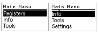|  |  |
eGauge support cannot provide the password currently set on a meter or the default password on meters shipped on or after Jan 2021.
 If you are not on the same local network and need to make changes, or reset the password [visit this KB article.](https://kb.egauge.net/books/egauge-meter-configuration/page/register-a-device-remote-access-and-password-resets "Register a device, remote access, and password resets") # Register a device, remote access, and password resets To only access a device interface, [visit this KB article.](https://kb.egauge.net/books/egauge-meter-configuration/page/accessing-egauge-interface "Accessing eGauge Interface") To register a device and get access, log in or create an [eGauge.net](https://egauge.net/) account at [https://egauge.net/login.](https://egauge.net/login) After being logged in, hover over eGuard, and click "Register a Device": 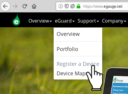 --- Enter the registration date, device name, and MAC address. The MAC address should start with F8-2F-5B. Enter the MAC without colons, dashes or spaces:  If you administrate an existing group, you will have the option to add the device to the group you admin. If the device being registered belongs to another group, after pressing Register Device it will tell you it cannot be moved but has been registered. --- Next, visit [eGauge.net/eGuard](https://egauge.net/eGuard) or hover your mouse over eGuard and click on Portfolio:  --- Locate the newly registered device in the portfolio and click the notepad icon to the left of the device name: 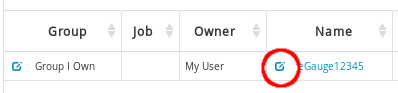 *Note: the "Name" to the right of the notepad icon is a link to the eGauge proxy-server URL* --- In the device details page, locate Remote Administration Control and press the Enable button:  The first username in the eGauge Access Control Settings now has remote administration enabled. Assuming the meter configuration hasn't been modified: For meters purchased on or after Jan 2021, the factory credentials are printed on the side of the meter. For meters purchased prior to Jan 2021, the factory credentials are user: **owner** pass: **default**. Note that these credentials may have been changed.eGauge support cannot provide the password currently set on a meter or the default password on meters shipped starting January 2021.
Make sure to change the password to something secure in **Settings -> Access Control**. If you administrate a group and the device was moved to it during registration (or automatically placed during the order process), there is also an option to reset a password for a user on the device: [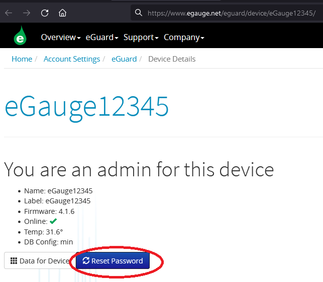](https://kb.egauge.net/uploads/images/gallery/2021-10/image-1633986631077.png) # Configuring CTid-enabled sensors ### What is CTid? CTid is a technology created by eGauge which allows the eGauge meter to obtain information about a connected CT or Sensor. This information can include model, manufacturer, serial number, amperage rating (if CT), and other information about the sensor. The information is stored on a chip embedded in the CT or Sensor, and can only be read by EG4xxx model units (eGauge Core and eGauge Pro). When inputs are scanned for CTid sensors, they are automatically configured instead of the user's traditional drop-down selection box. CTid enabled sensors also contain a locator LED that can be blinked from the eGauge configuration interface. This can be used to identify which sensor is connected to which port, in the event the leads were switched or untraceable.The CTid LED is OFF unless temporarily activated through the CTid configuration page in the meter interface.
### Prerequisites If you are not familiar with programming the eGauge, please refer to the [overview help page](https://egauge.net/help/overview) and ensure access and permissions to configure the eGauge before continuing. Ensure the sensors and Sensor Hub are [installed correctly](https://kb.egauge.net/books/sensors/page/sensor-hub-%28esh044%29) before continuing. ### Configuring CTid Sensors To configure a CTid-enabled sensor, navigate to the Installation Settings page (Settings -> Installation). Locate the blue "CTid" above the sensor drop-down menus: 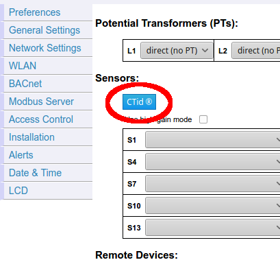 --- Next, select the sensor ports that have CTid-enabled sensors connected, and press "Scan Checked Sensors": [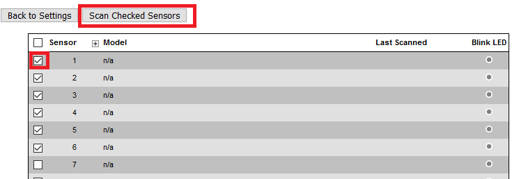](https://kb.egauge.net/uploads/images/gallery/2021-10/image-1635454977208.png) --- A green check-mark will show for each successfully detected sensor. The model and serial number is displayed for each sensor. Press the plus or minus sign (1) to expand or collapse additional information for the sensor. Every CTid sensor has an LED, which can be blinked by clicking the "Blink LED" button (2). To delete a configured sensor, press the "x" button (3). When finished, press "Back to Settings" to the left of the "Scan" button: [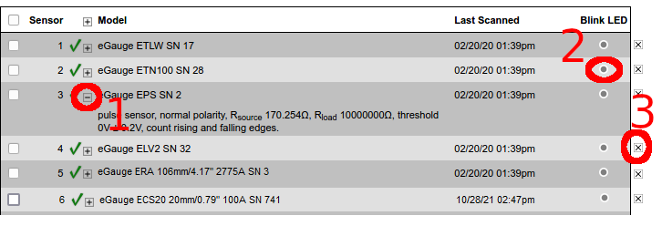](https://kb.egauge.net/uploads/images/gallery/2021-10/image-1635454598309.png) *In the above image, an ambient temperature sensor (ETLW) is connected to Sensor port 1. Port 2 contains a temperature probe sensor (ETN100), port 3 contains a pulse sensor (EPS), port 4 contains a low voltage or dry contact sensor (ELV2), port 5 contains a Rope CT (ERA-1206-2775) and port 6 contains a split-core CT (ECS20 20mm 100A).*The CTid blink LED function can also be activated via the LCD menu by choosing Tools > CTid. Move the toggle switch to choose which port to blink, then press the toggle switch to begin blinking the port. Press the toggle switch again to stop the blinking function.
--- Back in the Installation Settings page, the inputs will show the sensor detected in blue to indicate it was programmed via CTid: [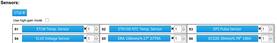](https://kb.egauge.net/uploads/images/gallery/2021-10/image-1635454915680.png) --- Finally, configure registers to record the data from these sensors: [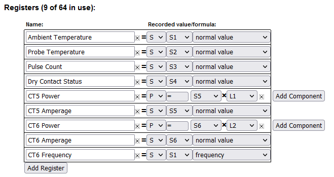](https://kb.egauge.net/uploads/images/gallery/2021-10/image-1635455244020.png) Choosing "S" (Sensor) for the type will record the value of the sensor. Temperature sensors record °C, pulse counts are unit-less, dry contact (low voltage sensor) records voltage and CTs record amperage. To record power, use "P" (Power) and choose the CT input (S5 iand S6 n this example) and the voltage line it is on. Instantaneous values may be found in the channel checker: [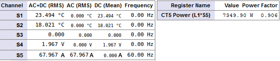](https://kb.egauge.net/uploads/images/gallery/2021-01/image-1610997332639.png) # Commissioning readings with the Channel Checker After configuring the eGauge, it is necessary to commission the readings to ensure accuracy using the channel checker. The channel checker can be accessed via **Tools -> Channel Checker**.   The Channel Checker tool provides instantaneous readings of all the inputs of the eGauge including voltage, amperage, watts, frequency and power factor. # Example: Good 3-phase solar  The left-side shows the channel inputs: the Line-Line voltages are ~500V, Line-Neutral are ~288V. Currents on CT1, CT2, and CT3 are between 640A and 660A. Only channels that are configured in a register will appear here. The right-side shows the registers and calculated power. Each leg of the solar inverter is outputting ~183kW, and have a good power factor of ~.98 (as expected by a solar inverter).For information on common physical issues that cause bad AC (RMS), DC (Mean) or frequency readings, [view this article](https://kb.egauge.net/books/troubleshooting/page/unexpected-readings-in-channel-checker).
# Example: Negated value on main usage  If a system with a neutral does not have any solar or other power back-feeding through the CTs, all power polarities should be the same. In this example, CT7\*L3 shows a negative value (-2259.8W), while CT8\*L2 and CT9\*L1 show positive power values. When these are added together in the register, CT7\*L3 reduces the overall power and will give inaccurate power values.| Cause | Fix |
|---|---|
| The CT is physically reversed (MOST COMMON) | Physically reverse the CT, or negate it in the Installation Settings register component (e.g., CT7\*L3 to -CT7\*L3) |
| Phase mix-up (MOST COMMON USUALLY W/ BAD POWER FACTOR) | Locate the correct phase and move the CT to it, or change the association in the Installation Settings register component (e.g., CT7\*L3 to CT\*L2). [Visit this KB article](https://kb.egauge.net/books/egauge-installation/page/panel-phasing-and-egauge-installation "Panel phasing and eGauge installation") for more information on phasing. |
| The CT black/white leads have been swapped | Swap the leads, or negate it in the Installation Settings register component. This is more common with CT extensions. |
| Multiple conductors in CT of different phases, or different directions | If multiple conductors are run through the CT with different phases, or different directions, it can cause polarity to randomly shift or stay at an unexpected polarity. Ensure only conductors of the same phase are in the CT. |
| Bad CT splices | If CTs have been extended or modified, sometimes they are mistakenly wired different on each end which can lead to combined signals that cause bad data. Ensure twisted pair wire is used. |
| CT not connected or insufficient amperage | If the CT is not connected the signal will bounce and can switch polarity. If there is no or insufficient amperage, noise can cause bad readings. |
| Wrong CT selected | Configuring with the wrong CT can cause the power to be negated or wrong. |
| False Positives | Reason |
|---|---|
| There is bidirectional power or back-feeding active | Power flowing through a CT in one direction gives a positive polarity, and if power reverses direction (like in back-feeding) the polarity negates. Make sure there is no back-feeding when troubleshooting polarity. |
| Cause | Fix |
|---|---|
| Phase mix-up (MOST COMMON, USUALLY W/ NEGATED VALUES) | Locate the correct phase and move the CT to it, or change the association in the Installation Settings register component (e.g., CT7\*L3 to CT\*L2). [Visit this KB article](https://kb.egauge.net/books/egauge-installation/page/panel-phasing-and-egauge-installation "Panel phasing and eGauge installation") for more information on phasing. |
| CT not clamped fully, or other damage | Ensure CT is fully clamped and undamaged. Some CTs take two clicks to fully close. |
| CT not configured correctly | If the type of CT is wrong (Rope, DC CT, AC CT), it can cause poor power factors and incorrect amperages. |
| False Positives | Reason |
|---|---|
| Active production from inverter on back-fed system (does not have to be actively back-feeding) | Solar and other inverters put out all real power, so as production increases on a back-fed system less real power is demanded from the utility and more reactive power, bringing the grid power factors down. This is normal. Run tests without any active production. |
| Insufficient amperage | When there is insufficient amperage on a CT (especially rope CTs), noise can cause higher than real amperage readings, and that noise is cancelled out when power is calculated resulting in a lower than real power factor. This is normal. |
| Equipment uses a lot of reactive power | Some equipment like HVAC systems can have a power factor of ~.5. |
When first installing a meter, it is **strongly recommended** to check the meter date and time (under **Settings -> Date & Time**) and manually update if necessary.
### Contents [Quick Troubleshooting Suggestions](#bkmrk-quick-troubleshootin-0) [Why do I need NTP?](#bkmrk-why-do-i-need-ntp%3F-0) [Configuration](#bkmrk-configuration-0) [Checking Status](#bkmrk-checking-status-0) [EG4xxx](#bkmrk-eg4xxx) [EG30xx](#bkmrk-eg30xx) [eGauge2](#bkmrk-egauge2) [NTP Functionality and Behavior](#bkmrk-ntp-functionality-an-0) [Functionality](#bkmrk-functionality) [General Behavior](#bkmrk-general-behavior) ### Quick Troubleshooting Suggestions If the meter date and time is incorrect or the meter isn't syncing with an NTP server: 1\. Navigate to **Settings -> Date & Time** and ensure the meter date and time is correct and a valid NTP server is entered. 2\. Verify the meter is on the [latest firmware](https://kb.egauge.net/books/egauge-meter-ui/page/checking-and-upgrading-firmware). 3\. Reboot the meter (either via the UI under **Tools -> Reboot** or by [manually power cycling](https://kb.egauge.net/books/general/page/how-do-i-power-cycle-the-egauge) the meter) and wait 5 minutes. See the [Checking Status section](#bkmrk-checking-status-0) of this document for more information on checking NTP synchronization status. If you do not know your meter password, visit [this article](https://kb.egauge.net/books/general/page/what-can-i-do-if-ive-lost-my-device-password). ### Why do I need NTP? The eGauge meter features an internal clock which can keep (approximate) time over short a short duration. However, without an active NTP connection the meter's internal clock may drift by as much as a few minutes per month. This may be acceptable for some users, but many monitoring scenarios require time-accurate data (e.g., for billing purposes). Furthermore, if the meter experiences an extended power outage the internal battery or capacitor which maintains the internal clock will be depleted. This will cause the meter to use the last known date and time when power is restored - meaning data recorded after that point will have the wrong timestamps. If the meter can connect to an NTP server when it's brought back online, it should automatically adjust the date and time *before it starts recording.* The amount of time a meter can maintain the correct date and time without power depends on the meter model:| Model | Charge Time | Run Time |
| EG4xxx | 5 minutes | 8 hours |
| EG30xx and eGauge2 | ~1 month | ~1 day |
eGauge Systems LLC cannot offer assistance or advice on creating or maintaining a local NTP server.
The NTP server hostname is configured under **Settings -> Date & Time**. In the following example, the meter is set to use the {0..3}.pool.ntp.org option mentioned previously: [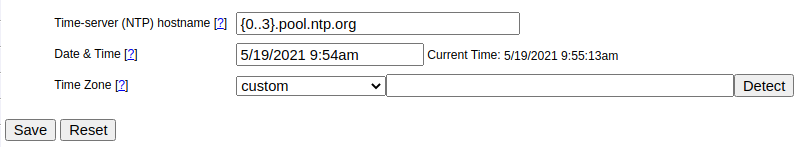](https://kb.egauge.net/uploads/images/gallery/2021-05/image-1621439743153.png)Make sure to click "Save" after making changes on this page. The meter will typically reboot after this step.
### Checking Status Although there is not a hard linked NTP status page built into the meter UI, it is possible to check the NTP status of a meter by appending /cgi-bin/get?ntp to the end of the meter URL. For example: DEVNAME.egaug.es/cgi-bin/get?ntp DEVNAME.egauge.io/cgi-bin/get?ntp HOSTNAME.local/cgi-bin/get?ntp LOCAL\_IP\_ADDR/cgi-bin/get?ntp Each meter hardware version uses a different method to obtain this data, and has a different output style:| Meter Version | Method Used |
| EG4xxx | ntpctl -s all ([OpenNTPD](https://man.openbsd.org/ntpctl)) |
| EG30xx | /usr/bin/ntpq -p ([ntpq](http://doc.ntp.org/3-5.93e/ntpq.html)) |
| eGauge2 | N/A (no data returned) |
For best results, ensure your meter is on the [latest firmware version](https://kb.egauge.net/books/egauge-meter-ui/page/checking-and-upgrading-firmware).
#### EG4xxx For an EG4xxx meter, the output will have a summary area at the top, along with some specific information for each peer: [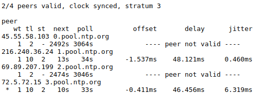](https://kb.egauge.net/uploads/images/gallery/2021-05/image-1621439978588.png) At the top of the page, the meter will list the number of valid peers. In this case, 2 of the four peers are valid. As long as one peer is valid, NTP synchronization should work as expected. Also at the top of the page, "clock synced" indicates the eGauge's internal clock is synchronized with the NTP server. It is normal for this to show "unsynced" for some time (up to five minutes) after a reboot. If the summary area is completely blank, it means the NTP daemon is not running. A reboot may resolve this issue. For more information on this output, see the [ntpctl manpage](https://man.openbsd.org/ntpctl). #### EG30xx For an EG30xx meter, the output will simply contain information on each connected peer (no summary area): [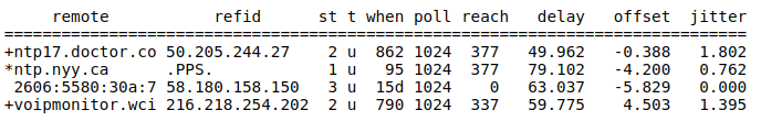](https://kb.egauge.net/uploads/images/gallery/2021-05/image-1621440683881.png) Valid peers (technically, peers marked for consideration) are preceded by a "+". The peer currently used for synchronization is preceded with a "\*". As long as at least one peer has a \*, NTP synchronization should work as expected. In the above example, three peers are valid and the meter is synced with one peer. This status page may be blank or not show any + or \* symbols for some time (up to five minutes) after a reboot. If the summary area is completely blank, it means the NTP daemon is not running. A reboot may resolve this issue. For more information on this output, see the [ntpq documentation](http://doc.ntp.org/3-5.93e/ntpq.html). #### eGauge2 eGauge2 meters use NTP to sync their internal clocks, but they do not provide a summary of connected peers. This is expected behavior and will not be changed due to meter hardware limitations. ### NTP Functionality and Behavior NTP timekeeping is a complex subject, and it would go beyond the scope of this article to fully explain. However, there are some basic concepts which are worth discussing here. For a more complete discussion of the subject, refer to [this article](https://www.ntp.org/ntpfaq/NTP-s-algo.htm). #### Functionality Put simply, an NTP server works by obtaining the correct date and time from a reference clock and making that date and time information available to a device. Reference clocks are generally extremely accurate (and as a result, extremely expensive). The internal clocks of most computing devices are generally *inexpensive*, but also not very accurate. NTP serves as a software-based solution to this problem. NTP servers may be run and hosted by anyone, including home users. The NTP software running on the eGauge uses several criteria to determine the quality of an NTP server. The criteria for this is too complex to detail here, but the takeaway is that the meter will automatically handle sever selection and use the best (most accurate and accessible) available servers. This is where the **strata** statistic comes in - strata indicates the quality of a server, with 1 being the best quality. Typically, all of this happens "behind the scenes" (this is also true for other computing devices, including personal computers). However, in certain cases it may be necessary to check the meter's NTP status (to ensure it's reaching a valid server) or modify settings (if the default servers can't be reached). #### General Behavior On bootup (e.g., after a reboot or when first installed), the eGauge will attempt to establish a connection to an NTP server. At this point, the meter may make a long jump to the correct date and time. This is technically referred to as a "step", using the settimeofday() function. This jump happens **instantaneously**, but it may *only* happen immediately after a reboot. However, if it takes too long to find an NTP server (e.g., because the network is not ready, because the NTP server is not resolvable, etc.) the meter may "miss" its chance to do this. Often, rebooting the meter will allow it to sync on the second try. At any time during normal operation, the eGauge may attempt to slowly adjust the meter date and time to match the date and time provided by the NTP server. This is known as a "slew", using the adjtime() function. Unlike a "step", a "slew" will slowly change the date and time at a rate of about 1 ms per second. For example, a clock offset of 1 second would take about 1000 seconds or 16 minutes to sync up. Obviously this is much slower than a "step", but "slew" is really only intended to handle small changes. This is also part of the reason a meter may take several minutes to show "synced" status after a reboot - a reboot introduces about a 120ms offset into the date and time, which would take about 2 minutes to sync back up using "slew". # Advanced Configuration Advanced meter configuration (above and beyond monitoring real power). # Voltage registers Voltage registers are configured in much the same way as power registers (the default register type on the eGauge). To add a voltage register: ### Firmware 4.0 and newer 1. Navigate to **Settings -> Installation** 2. Under **Registers**, click the "Add Register" button 3. Name the register as appropriate 4. Using the dropdown menu, change the register type from "P" to "L" [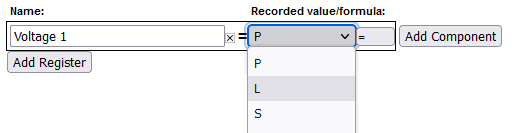](https://kb.egauge.net/uploads/images/gallery/2023-06/image.png) 5. In the next dropdown menu, select the appropriate voltage reference. • L1, L2, L3 use the high-voltage AC line inputs relative to N terminal • L1-L2, L2-L3, L3-L1 use the high-voltage AC line inputs as line-to-line voltages • D1, D2, D3 use the high-voltage AC line inputs with a virtually calculated neutral (**not commonly used and** **still requires N connection**) • Ldc uses the 2-pin DC voltage input [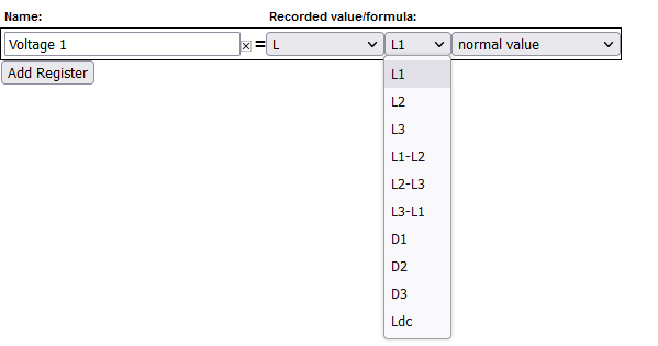](https://kb.egauge.net/uploads/images/gallery/2023-06/kpRimage.png) 6. In the final dropdown menu, select the measurement type • "normal value" records RMS voltage (e.g., for AC voltages) • "DC-only (mean) value" records the mean value (e.g., for Ldc input) • "frequency" records the frequency of the input. Frequencies are counted as zero-level crosses, so DC voltages will typically display 0 Hz. [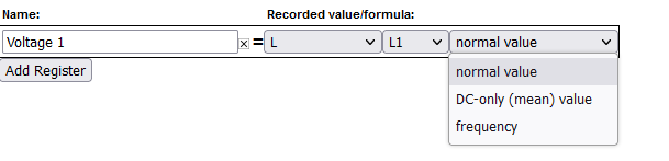](https://kb.egauge.net/uploads/images/gallery/2023-06/eT9image.png) 7. Click "Save" at the bottom of the page when finished (valid credentials required) As with all physical registers, data will only start recording from the time the register is created. It is also possible to set up a formula register to evaluate the *difference* between two voltage registers. This can be used to trigger an alert, or just to obtain a historical reference. It is typically not required for the average installation. To create this register: 1. Navigate to **Settings -> Installation** 2. Under **Registers**, click the "Add Registers" button 3. Name the register as appropriate 4. Using the dropdown menu, change the register type to "=" 5. A second dropdown menu will appear. Set the unit type to "voltage \[V\]" 6. In the formula field, enter the following: `abs($"VL1"-$"VL2")` where `VL1` and `VL2` are the names of voltage registers. The order does not matter. Click "Save" at the bottom of the page when finished (valid credentials required)  ### Legacy (pre firmware 4.0) 1. Navigate to **Settings -> Installation** 2. Under **Registers**, click the "Add Registers" button 3. Name the register as appropriate 4. Using the dropdown menu, change the register type from "P" to "V" 5. A second dropdown menu will appear. Select the appropriate voltage reference 6. Click "Save" at the bottom of the page when finished (valid credentials required) 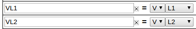 # Amperage Registers The eGauge can be set to record individual CT amperages as separate registers. Unlike power registers, amperage registers are absolute values (they do not change polarity to reflect the directional flow of current). ### Firmware 4.0 and newer To add amperage registers: Navigate to **Settings -> Installation** Under **Registers**, click the "Add Registers" button Name the register as appropriate Using the dropdown menu, change the register type from "P" to "S" In the next dropdown menu, select the appropriate sensor number In the final dropdown menu, select the measurement type (if in doubt, "normal value" is generally correct) Click "Save" at the bottom of the page when finished (valid credentials required)  As with all physical registers, data will only start recording **from the time the register is created**. ### Legacy (pre firmware 4.0) To add amperage registers: Navigate to **Settings -> Installation** Under **Registers**, click the "Add Registers" button Name the register as appropriate Using the dropdown menu, change the register type from "P" to "I" A second dropdown menu will appear. Select the appropriate CT number Click "Save" at the bottom of the page when finished (valid credentials required)  # Power Register Subtypes By default, the eGauge will record Power registers as the "Net" (=) subtype. This means the register will record power flow in both directions. Positive readings will be graphed as a green line, and negative readings as a red line. However, it is possible to record other subtypes as well. Some of these are needed for basic calculations (such as positive-only subtypes) while others can be used in advanced calculations (the apparent power subtype). The full list is below: - net (=) - Records both positive and negative power readings. Default, recommended setting for all power registers. - positive-only (+) - Records only positive values. Negative values are converted to zeros. Cannot be selected at the same time as negative-only (-). - negative-only (-) - Records only negative values. Positive values are converted to zeros. Cannot be selected at the same time as positive-only (+). - absolute (|) - Records the absolute value of the total power calculation. Be aware, the order of operation is to calculate the total power of all components in the register and then record the absolute value of that. For example, if the register calculation is `CT1*L1 + CT2*L2`, and `CT1*L1` is -500 W and `CT2*L2` is +300 W, the absolute value recorded will be 200 W (not 800 W). - apparent (\*) - Records apparent power (VA), does not take power factor into account.  Power Register Subtypes To select a power register subtype, click the small box containing the "=" sign that appears to the right of the "P" indicating a power register. Select the appropriate subtypes and click the OK button. Subtypes are named based on the original (net) power register's name and their subtype sign. For example, a power register named "Grid" recording net, apparent, and positive-only power would exist as "Grid", "Grid\*", and "Grid+". Each subtype selection uses an additional register in the eGauge database.  Grid Register with Multiple Subtypes # Power Factor Although the eGauge uses power factor to calculate real power, the power factor values are not stored in the database by default. However, it is possible to create a register to track the power factor of either a single CT/phase pairing or aggregate registers containing multiple CT/phase pairings. This requires both a Real Power and Apparent Power register already be configured (see [Power Register Subtypes](https://kb.egauge.net/books/egauge-meter-configuration/page/power-register-subtypes "Power Register Subtypes")). Power registers can contain a single CT/phase pairing or multiple CT/phase pairs. Any set of real power and apparent power registers can be used to calculate power factor. If unsure how to create an apparent power register, please see [Power Register Subtypes](https://kb.egauge.net/books/egauge-meter-configuration/page/power-register-subtypes "Power Register Subtypes"). In the example below, there are eight registers. Four real power (Grid, S1xL1, S2xL2, S3xL3) and four apparent power registers (Grid\*, S1xL1\*, S2xL2\*, S3xL3\*).  To record power factor for a given real power and apparent power register set: Navigate to **Settings -> Installation** Under **Registers**, click the "Add Registers" button Name the register as appropriate Using the dropdown menu, change the register type from "P" to "=" A second dropdown menu will appear. Select the unit type "Number with 3 decimals" In the formula field, enter the following: abs($"**REGNAME**"/$"**REGNAME**\*") where **REGNAME** is the name of the power register (type P). Note the \* present after the second instance of **REGNAME**. Click "Save" at the bottom of the page when finished (valid credentials required) [](https://kb.egauge.net/uploads/images/gallery/2022-02/image-1645728925640.png) Sample Power Factor Register (using the registers "Grid" and "Grid\*") # THD RegistersTHD is a measurement of the harmonic distortion of a signal given it's fundamental frequency, and thus may be larger than 100%. If there is insufficient amperage on a CT or the circuit is not active, the noise may calculate to high percentages.
THD is typical on current waveforms depending on the load and is not always a cause for concern.
The eGauge can calculate Total Harmonic Distortion (THD) on a given CT or voltage reference. Each THD measurement will use one physical register. The eGauge can measure up to the 10th harmonic. To measure THD, 1. Navigate to **Settings -> Installation** 2. Under **Registers**, click the "Add Registers" button 3. Name the register as appropriate 4. Using the dropdown menu, change the register type from `P` to `=` 5. A second dropdown menu will appear. Select the unit type to "total harm. dist" or "THD \[%\]" In the formula field, enter the following: `THD(Hz, chan("XX"))` where **`Hz`** is the system frequency in Hz and **`XX`** represents either a CT (CT1, CT2, CT3, etc) or a voltage reference (L1, L2, L3). Click "Save" at the bottom of the page when finished (valid credentials required)  Sample THD Register for CT1 on a 60Hz system **Firmware 4.0 and later:** CTx channel names have been replaced with Sx channel names. Thus, instead of using `chan("CT1")`, use `chan("S1")`. Configuration is otherwise identical:  #### See also - [eGauge Waveform View](https://kb.egauge.net/books/egauge-meter-ui/page/waveform-view) # Configuring Unsupported CTs ### Custom CT size scale factor Calculation Always use caution when choosing to use unsupported CTs with the eGauge meter. Supported sensors are always preferred and will yield the most accurate results.eGauge Systems cannot guarantee accuracy or safety when using unsupported CTs. Do not connect current output CTs to the sensor ports.
Please refer to section B.6 of your owner's manual for details on choosing compatible CTs. #### EG4xxx meters: `-20669.22 / CT_AMPS = SCALE_FACTOR` #### EG30xx and eGauge2 meters: The general format for calculating a custom CT scale factor is: `1227 / CT_AMPS = SCALE_FACTOR` For example: `1227 / 600 = 2.045` This is not exact, as we test each CT specifically. Also, if the CT polarity is reversed on the custom CT, the scale factor will need to be negated. Configure the CT as in the example below using your calculated scale factor: [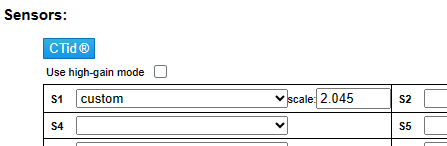](https://kb.egauge.net/uploads/images/gallery/2023-06/1zQcustom-ct.png) # Connection Quality The eGauge can record network connection quality as a percentage value (0..100). This information is displayed on the **Status** page (http://**DEVNAME**.egaug.es/status.html where **DEVNAME** is the [device name](https://kb.egauge.net/books/general/page/where-can-i-find-my-device-name "Where can I find my device name?") of your eGauge meter) under "Connection Quality" by default, but historical values are not stored. Storing network connection quality as a register may be useful for certain types of troubleshooting (for example, to determine if the HomePlug signal is interrupted by a certain piece of equipment turning on/off). Note that this value updates once a minute (not necessarily at the top of the minute).For devices sold after January 1, 2024 this information can be seen at: https://**DEVNAME**.egauge.io/status.html where **DEVNAME** is the [device name](https://kb.egauge.net/books/general/page/where-can-i-find-my-device-name "Where can I find my device name?") of your eGauge meter.
To record network connection quality: Navigate to **Settings -> Installation** Under **Registers**, click the "Add Registers" button Name the register as appropriate Using the dropdown menu, change the register type from "P" to "=" A second dropdown menu will appear. Select the unit type to "number" In the formula field, enter the following: conn\_qual() (note that nothing should be entered between the parentheses) Click "Save" at the bottom of the page when finished (valid credentials required)  Sample Connection Quality register using conn\_qual() Note that this function is available on the EG30xx and EG4xxx hardware. It is **not** available on the eGauge2. conn\_qual() tracks the connection quality of whatever network interface is in use, and does not need to be modified or adjusted if the network interface is changed (for example, if switching from HomePlug to Ethernet communication). As with all physical registers, conn\_qual() will only start recording data from the time it is created. # Net import/export registers on line side tap system On a backfed PV installation (that is, an installation where excess solar production is fed back through a breaker on the main distribution panel to the utility) it is relatively easy to see the net import and export of power. The CTs installed on the main utility feeds are in effect **net** CTs, as they see power imported from and exported to the utility. Any register created using those CTs will thus change polarity when production exceeds consumption, and change back when consumption exceeds production. For instructions on displaying the net import/export values for a backfed system, see [this article](https://kb.egauge.net/books/egauge-meter-configuration/page/net-usagegeneration-registers-on-a-backfed-system "Net Usage/Generation Registers on a Backfed System"). However, a line side tap PV installation (where the solar is tapped between the main utility feed CTs and the utility meter itself) only tracks the consumption of the main distribution panel by default. A register using the main utility feed CTs will only see the consumption associated with that panel, regardless of how much production is being fed back to the utility. In this case, a comparison between the main utility CTs ("Grid" register) and the production CTs ("Solar" register) can show how much power is being imported or exported. To track this information, two formula registers must be created as follows:  Figure 1: Sample Net Import/Export register setup Net In = min($"Solar" - $"Grid",0) Net Out = max($"Solar" - $"Grid",0) Note that this assumes two registers, one named "Grid" which tracks **only consumption** on the main distribution panel, and one name "Solar" which tracks total solar production. If needed multiple registers can be combined.A new register will not contain any historical data. There is no way to backfill historical data into a new register.
The next step is to create a new view to display the net import and net export registers properly. To do this: 1\. Under "Totals and Virtual Registers", create two new virtual registers "Net.Usage" and "Net.Generation". 2\. Set Net.Usage equal to "Net In", and Net.Generation to "Net Out". When done, they should look like this: [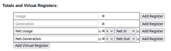](https://kb.egauge.net/uploads/images/gallery/2022-02/image-1644876431003.png)Figure 2: Virtual Register Configuration 3\. Save your changes and reboot if prompted. Once the register split process has been completed, data can be viewed on the main graph page by selecting the "Net" view. The images below show a comparison between the default "total used/total generated" graph and the new "net used/net sold" graph. [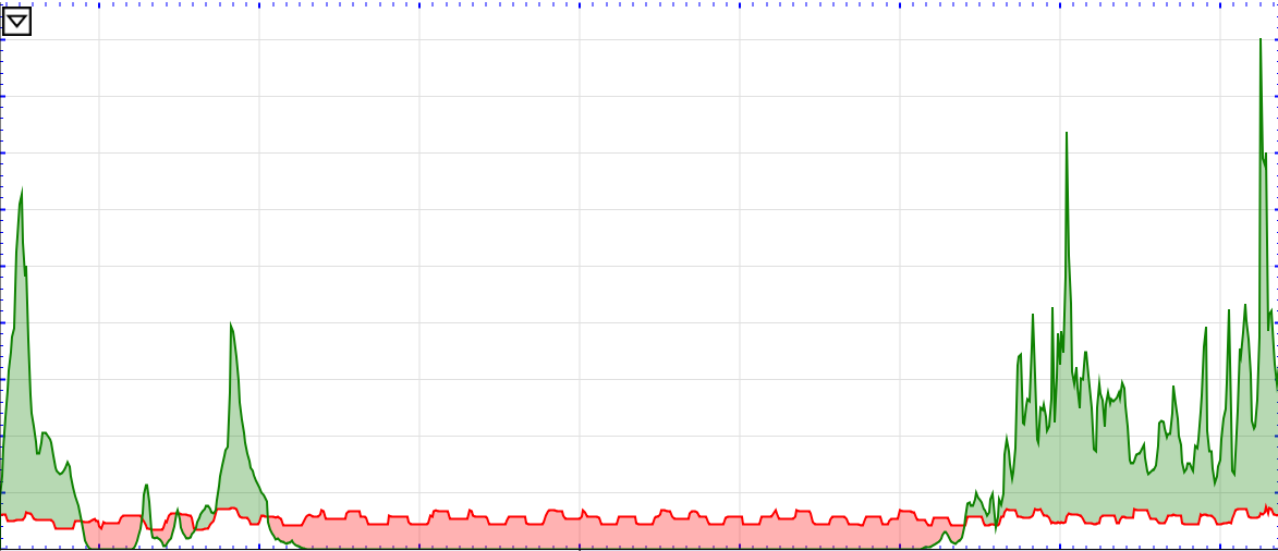](https://kb.egauge.net/uploads/images/gallery/2022-02/image-1644876492286.png) Figure 3: Default view (note overlapping Usage and Generation lines) [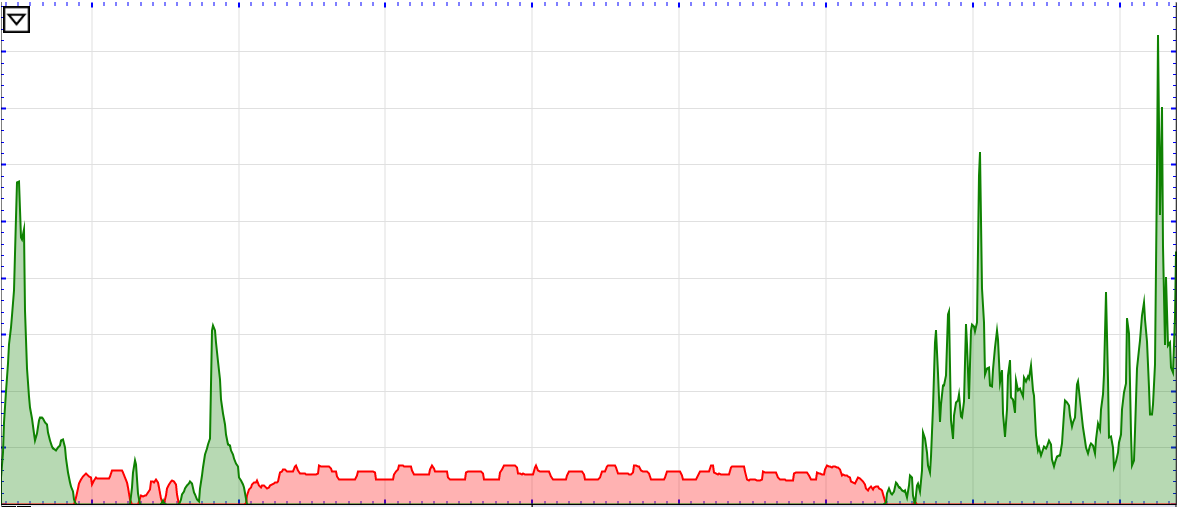](https://kb.egauge.net/uploads/images/gallery/2022-02/image-1644876549848.png)Figure 4: Net view (note power is either moving to or from the utility) # Net import/export registers on a backfed system In some cases, it can be useful to graph the net flow of power to and from the utility, instead of the total power consumed and produced. This process adds a new view to display this information. The instructions below only apply to backfed PV systems - use [these instructions](https://kb.egauge.net/books/egauge-meter-configuration/page/net-importexport-registers-on-line-side-tap-system "Net import/export registers on line side tap system") for lineside tap installations. Note that valid credentials are needed to apply these changes. These instructions also assume that these registers are being added to an existing installation. Steps 6-7 can be skipped on a fresh installation. 1\. Navigate to **Settings -> Installation** and verify the "Usage" register at the bottom of the page contains "Solar+". This will *not* work with devices which are not using "Solar+" in the "Usage" register. 2\. Set the "Grid" register to [record both positive and net values](https://kb.egauge.net/books/egauge-meter-configuration/page/power-register-subtypes "Power Register Subtypes"). When done, it should look like this:  Figure 1: Grid register configuration 3\. Add two new virtual registers: "Net.Usage" and "Net.Generation". Note the spelling and capitalization must match *exactly*. 4\. Set "Net.Usage" to equal "Grid+" and "Net.Generation" to equal "Grid-". When done, they should look like this:  Figure 2: Virtual register configuration 5\. Save and reboot. 6\. Once the eGauge comes back online, navigate to **Tools -> Split Registers**. 7\. Select "Grid" and click Start Splitting. This process can take 10-15 minutes - *do not* reboot the eGauge during this time. Once the register split process has been completed, data can be viewed on the main graph page by selecting the "Net" view. The images below show a comparison between the default "total used/total generated" graph and the new "net used/net sold" graph.  Figure 3: Default view (note overlapping Usage and Generation lines)  Figure 4: Net view (note power is either moving to or from the utility) # Reactive Power (kVAr) Reactive power can be recorded using a formula register. First, create a power register for the equipment monitored:  Next, click the power sub-type selector box to the right of the "P" box:  Choose "\* Record **apparent power**" and press OK:  Finally, add a new register, change the "P" box to an equals sign for a formula register, choose "react. power \[var\]" as the unit, and enter a formula of: ``` VAr($"registername", $"registername*") ``` where **registername** is the name of the power register. Note the asterisk (\*) on the end of the second register name - this references the apparent power register.  # Potential Transformer ConfigurationeGauge Systems cannot guarantee meter accuracy when third party potential transformers are used. It is recommended to use the **[EV1000 high voltage sensor](https://kb.egauge.net/books/egauge-hardware-product-pages/page/egauge-high-voltage-sensor-ev1000)** when measuring a high voltage system (480V no-neutral, 347V no-neutral or 600V system), or on a different side of a transformer from where the eGauge is connected.
The eGauge AC voltage inputs can handle up to 277Vrms between any line input (L1, L2, L3) and neutral terminal. If voltages exceed this range, potential transformers must be used to step-down the voltage from the system to the eGauge voltage input terminals. When using a potential transformer, the eGauge must be configured appropriately in Settings -> Installation -> Potential Transformers. Generic options such as 277:120 and 480:120 are available, as well as specific supported transformer models, such as FDT-480-120. A set of negated transformer values are also available. Choosing this negates the polarity of the voltage. This has the effect of negating all power calculations using this transformer setting. The PT ratio is configured in Settings -> Installation under the PT section. To use a custom ratio, choose "custom" and enter the scale factor: [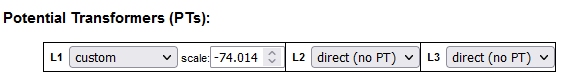](https://kb.egauge.net/uploads/images/gallery/2022-09/image-1663022952711.png) # Custom potential transformer ratios If a custom, unsupported step-down transformer ratio is used but not available in the drop-down menu, a custom scale factor will need to be used. To calculate a custom potential transformer scale factor, use the following calculation: secondary / primary \* model\_pt\_value = SCALE\_FACTOR where:| secondary | is the secondary voltage |
| primary | is the primary voltage |
| model\_pt\_value | is a model-specific value (see below) |
| SCALE\_FACTOR | is the custom scale factor you should use on the eGauge2 and EG30xx |
| EG4xxx (with LCD display) | -74.0140 |
| EG30xx (no LCD, w/ Ethernet) | -4.003 |
| eGauge2 (no Ethernet, no LCD) | -4.003 |
The blue "i" button to the right of the question mark button will provide debug output after the remote device is resolved. If the remote device fails to resolve, this debug information can help determine why.
The remote device will need to be re-verified every time the Installation page is reloaded.
##### Reading From A Remote Device To actually record data from a remote device, it must first be verified using the process above. Assuming that is successful, create a new register in the "Registers" section by clicking the "Add Register" button. Select a name for the new register. Using the dropdown menu, change the default "P" to the remote device name. A second dropdown menu will appear - select the appropriate register from the list. Make sure to click "Save" at the bottom of the page to save these changes. [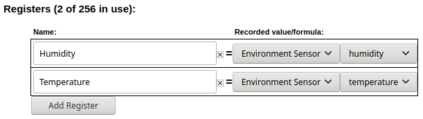](https://kb.egauge.net/uploads/images/gallery/2021-01/image-1611350804053.png) In the example above, the eGauge is set to record two registers from the remote device "Environment Sensor". --- ### Supported Protocol ConfigurationSome protocols are deprecated or unsupported and are not documented here.
#### Remote eGauge via UDP/TCP These protocols are used to have a master eGauge meter read from a secondary eGauge meter. There are two options available - UDP or TCP. This can be used at installations where multiple eGauge meters are present to allow the end user to see a single consolidated view instead of navigating to multiple meters. This protocol is only supported by eGauge meters, and cannot be used with third party devices. ##### Remote eGauge Device Address Format UDP is generally the more stable and reliable option, but only works over local networks where UDP access is available. The Device Address string is simply the [device name ](https://kb.egauge.net/books/general/page/where-can-i-find-my-device-name)of the remote eGauge. An IP address can also be used, but the meter should either be set to use a [static IP](https://kb.egauge.net/books/connectivity/page/how-do-i-configure-a-static-ip-address) address or assigned a DHCP lease reservation. TCP uses a connection over TCP port 80 instead of UDP. The Device Address can be a [device name](https://kb.egauge.net/books/general/page/where-can-i-find-my-device-name), IP, or FQDN (do not specify "http://" or use any slashes in the address). A TCP connection can be established over the eGauge proxy server, meaning it's possible to pull data from meters at multiple sites into a single master eGauge. However, this connection may be unstable.Remote devices with site-wide password protection will not allow for remote eGauge via TCP to be used.
The example below shows a master meter configured to read from "eGauge52002" via both UDP and TCP. [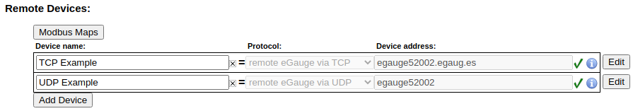](https://kb.egauge.net/uploads/images/gallery/2021-01/image-1611351873016.png) --- #### ### Serial This protocol is used for devices being read over a serial line. This includes Modbus RTU (both SunSpec and non-SunSpec), SMA and Power-One via serial. Serial data can be read over a local USB port on the EG4xxx using a [USB to RS485 converter](https://kb.egauge.net/books/egauge-hardware-product-pages/page/egauge-usb-serial-converter-%28usb485%29), or on the EG30xx and EG4xxx meters using [RS485 to Ethernet converter](https://kb.egauge.net/books/egauge-hardware-product-pages/page/rs485-to-ethernet-converter-%28bf430%29) over a local network (LAN). ##### Modbus RTU Serial Protocol The device address for serial devices is as follows: `modbus://DEVTYPE.SERIAL_ADDR@CONV_ADDR:PARAMETERS` where: `DEVTYPE` is the device type. This can be the name of a Modbus map. See [this article](https://kb.egauge.net/books/egauge-meter-communication/page/creating-sharing-and-using-modbus-maps) for information on how to find and create Modbus maps. `SERIAL_ADDR` is the serial address (also referred to as the slave address, device ID, or unit ID) of the remote device. `CONV_ADDR` is the address of the serial converter. For USB-serial converters, this can be `USB1` or `USB2` (case-sensitive). If using a serial-to-Ethernet converter, this can be the hostname, MAC address, or IP address of the converter. `:PARAMETERS` are additional addressing parameters which may be specified. If using a USB485 converter, the format is `:BAUD/[DATA_BITS][PARITY][STOP_BITS]`. BAUD is the baud, DATABITS is the number of data bits, PARITY is `n` for "none", `e` for "even" or `o` for "odd", and STOP\_BITS are the number of stop bits. Examples include `:9600/8n1` and `:19200/8e1`. It is most typical to have 8 data bits, no parity, and 1 stop bit. If the Modbus map defines default serial parameters, this may be excluded. If using an Ethernet-serial converter, `:PARAMETERS` specifies a TCP port. If omitted, the eGauge defaults to use port 50,000 which is the default for the support BF-430 converter. ##### Examples `modbus://imt_si.1@USB1` `modbus://cps403x.5@USB2:9600/8n1` `modbus://ae75_100tx.1@192.168.1.241` Note this is using an IP address to specify a serial-Ethernet converter like the BF-430. #### SMA Serial Protocol Legacy SMA serial devices may be configured in the format of: `sma://@CONV_ADDR` where: `CONV_ADDR` is the address of the serial converter. For USB-serial converters, this can be `USB1` or `USB2` (case-sensitive). If using a serial-to-Ethernet converter, this can be the hostname, MAC address, or IP address of the converter. ##### Example [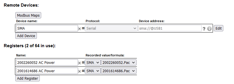](https://kb.egauge.net/uploads/images/gallery/2021-09/image-1631564795869.png) Note: The SMA serial protocol self-defines register names and are prefixed by the serial number of the device being read from. In the above example, "Pac" is the AC Power for the prefixed serial number. #### Power-One Aurora Serial Protocol Legacy Power-One Aurora serial devices may be configured in the format of: `po://UNIT_ID@CONV_ADDR` where: `UNIT_ID` is an optional ID of the inverter being read from. This may be omitted to perform auto-discovery. If auto-discovery fails, please specify the UNIT\_ID in a separate remote device address for each inverter on the serial chain. `CONV_ADDR` is the address of the serial converter. For USB-serial converters, this can be `USB1` or `USB2` (case-sensitive). If using a serial-to-Ethernet converter, this can be the hostname, MAC address, or IP address of the converter. ##### Example [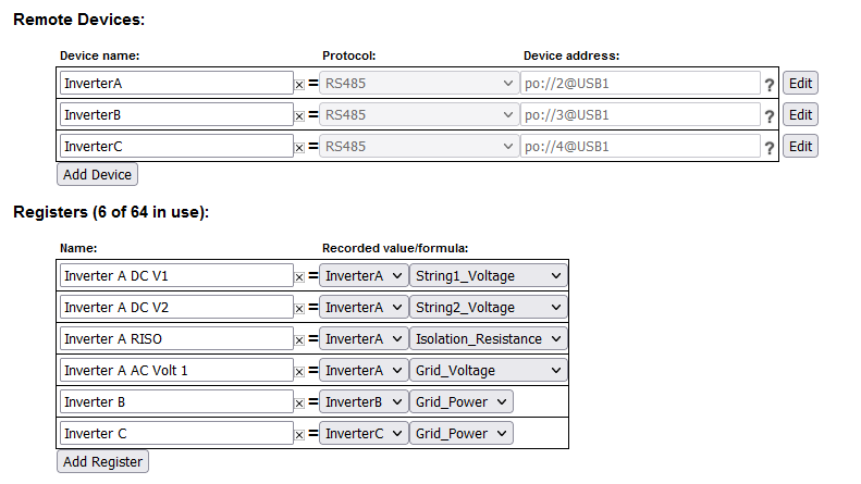](https://kb.egauge.net/uploads/images/gallery/2021-09/image-1631565558891.png) --- #### ### Modbus TCP Modbus TCP is a protocol that operates over a local TCP/IP network. The remote device must be connected to the same local network as the eGauge.Using Modbus TCP over the internet (across networks) is unsafe and not supported.
##### Modbus TCP Device Address Format The device address format for Modbus TCP is as follows: `DEVTYPE.UNIT_ID@ADDR:TCP_PORT` where: `DEVTYPE` is the name of a Modbus map. See [this article](https://kb.egauge.net/books/egauge-meter-communication/page/creating-sharing-and-using-modbus-maps) for information on how to find and create Modbus maps. `.UNIT_ID` is the unit ID (also referred to as slave address or device ID) of the Modbus device. If omitted, this defaults to 255. Some Modbus TCP devices do not care what unit ID is specified. `ADDR` is the address of the Modbus device. This may be an IP, hostname, or FQDN. `:TCP_PORT` is optional to specify a non-default Modbus TCP port. If omitted, this defaults to the standard Modbus TCP port of 502. ##### Examples [`cps403x@192.168.1.242`](mailto:cps403x@192.168.1.242) --- #### ### ControlByWeb The eGauge can read from many ControlByWeb products that are network-enabled. This includes the X-320, X-410, X-420 and others. These ControlByWeb devices run a local webserver which the eGauge can read from over the local network. Communication is handled through HTTP requests, meaning only local communication (over the same network) is supported. ##### ControlByWeb Device address format The format for the remote device is simply the IP address of the ControlByWeb device. The ControlByWeb hardware must have a static IP configured or DHCP reservation on the network so the IP address doesn't change unexpectedly. [](https://kb.egauge.net/uploads/images/gallery/2021-02/image-1612543493002.png) The following data points are supported. Note that X indicates a there may be multiple data points of that type available (this depends on the model). For example, "countX" could be "count1", "count2", and so on. frequency (frequency input) vin (voltage powering the CBW device) countX (pulse reading) analogInputX (analog input value) oneWireSensorX (one wire temperature sensors) sensorXtemp (temperature sensors) extvarX (external variable) digitalIOX (binary digital IO value) Although the eGauge can read from ControlByWeb devices, CBW hardware is not officially supported by eGauge Systems. For configuration questions on the CBW hardware itself, [contact ControlByWeb directly](https://www.controlbyweb.com/contact.html). For questions regarding whether a specific ControlByWeb model is compatible with the eGauge, [contact eGauge support directly](mailto:support@egauge.net?Subject=CBW%20Inquiry). # Logging data from pulse metersThis article describes using pulse sensors to read from energy meters, but any meter such as flow meters may be used. The only difference is to change the formula register from "Power \[W\]" to the particular measurement and using a "constant" that represents 1 unit (per pulse) of that measured item, for example cubic meters if volumetric flow. If the eGauge does not support the measured item, "number with 3 decimals" may be used instead.
The eGauge [Pulse Sensor (EPS)](https://kb.egauge.net/books/egauge-hardware-product-pages/page/pulse-sensor-%28eps%29) can be used to monitor a dry contact pulse output from many different types of devices, including energy meters equipped with a KY (2-wire) or KYZ (3-wire) pulse output, sometimes referred to as Form A or Form C, respectively. Using pulse to monitor power and energy values results in less-granular data than using physical voltage references and CT amperage readings, due to the fact pulse meters only indicate when one or more cumulative energy units (e.g., 1 kWh or 50 Wh) have been used. ### Physical Connection KY and KYZ pulse outputs designate "K" as "common" which is always used in KY or KYZ applications. The eGauge Pulse Sensor (EPS) is a "KY" connected sensor. The "K" (common) should go to the EPS ⏚ (ground) terminal, and either Y or Z to the SIG (signal) terminal. #### KY (2-wire) vs KYZ (3-wire) In simple terms, if "Y" is closed, "Z" is open. If "Z" is closed, "Y" is open. Therefore, only Y or Z (in conjunction with "K") is needed to detect pulses. The eGauge Pulse Sensor (EPS) is a 2-wire KY style sensor, so either the Y or Z wire is used and does not matter which. ### Net Metering (consumption and generation) KY and KYZ pulse outputs can only indicate the increase (and not decrease) of a single reading. For example, if a net meter is able to spin both directions (one direction for utility draw, and the opposite for back-feeding to the utility), a single KY or KYZ output is not able to represent both directions, as pulse values only change from closed to open, and open to closed, not indicating which direction (draw or back-feed) it is for. Thus, with bidirectional power, there should be 2 independent KY or KYZ pulse outputs, requiring two EPS sensors, one for utility draw and another for back-fed power to the utility. ### Configuration 1. Using CTid, [configure the sensor input](https://kb.egauge.net/books/egauge-meter-configuration/page/configuring-ctid-enabled-sensors)and create a register for the pulse count, where "S1" is the sensor input the EPS is connected: [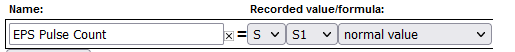](https://kb.egauge.net/uploads/images/gallery/2021-08/image-1629827906288.png) 2. Create a power formula register to calculate the power reading from the pulse count. The formula register contents should be: `$"Pulse Register" * constant * 3600` where `Pulse Register` is the register name of the register recording the pulse count, and `constant` is the meter Wh constant factor (effectively, in watt-hours what one pulse indicates or "Wh-per-pulse"). The below screenshot shows the calculation for a single pulse representing 5.3 watt-hours: [](https://kb.egauge.net/uploads/images/gallery/2022-11/pulse-meter-formula.png) #### Math behind the formula register The reason 3,600 is multiplied by the Wh-per-pulse is due to the meter reading data at second-granularity and there being 3,600 seconds in one hour. For example, if there is a meter constant of "1" (meaning 1 pulse is 1 Wh), when the eGauge meter receives 1 pulse, it will record "1" at that second in time, which will show as 1 watt during that 1 second it was detected (1 watt-second of energy). To convert watt-seconds to watt-hours, we multiply by 3,600 seconds. If a single pulse represents kWh rather than Wh, the formula will need to be multiplied by 1,000, such as: `$"Pulse Register" * constant * 3600 * 1000` ### Miscellaneous Notes Pulse meters change output state each pulse; that is, the output goes from open to closed to indicate a single pulse, than open to closed to indicate the next pulse, and alternates continously for each pulse. If testing the pulse sensor and recorded data by shorting the SIG and GROUND terminals, contacting will result in 1 pulse, and releasing will result in an additional pulse.