Advanced Configuration
Advanced meter configuration (above and beyond monitoring real power).
- Voltage registers
- Amperage Registers
- Power Register Subtypes
- Power Factor
- THD Registers
- Configuring Unsupported CTs
- Connection Quality
- Net import/export registers on line side tap system
- Net import/export registers on a backfed system
- Reactive Power (kVAr)
- Potential Transformer Configuration
- Frequency Registers
Voltage registers
Voltage registers are configured in much the same way as power registers (the default register type on the eGauge). To add a voltage register:
Firmware 4.0 and newer
- Navigate to Settings -> Installation
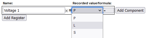
- Under Registers, click the "Add Register" button
- Name the register as appropriate
- Using the dropdown menu, change the register type from "P" to "L"

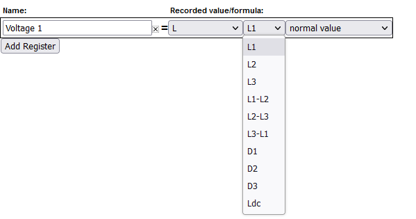
- In the next dropdown menu, select the appropriate voltage reference.
• L1, L2, L3 use the high-voltage AC line inputs relative to N terminal
• L1-L2, L2-L3, L3-L1 use the high-voltage AC line inputs as line-to-line voltages
• D1, D2, D3 use the high-voltage AC line inputs with a virtually calculated neutral (not commonly used and still requires N connection)
• Ldc uses the 2-pin DC voltage input

-
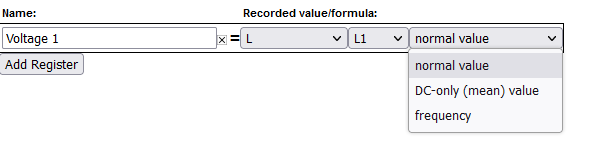
In the final dropdown menu, select the measurement type
• "normal value" records RMS voltage (e.g., for AC voltages)
• "DC-only (mean) value" records the mean value (e.g., for Ldc input)
• "frequency" records the frequency of the input. Frequencies are counted as zero-level crosses, so DC voltages will typically display 0 Hz.
-
Click "Save" at the bottom of the page when finished (valid credentials required)
As with all physical registers, data will only start recording from the time the register is created.
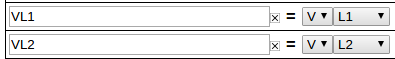
It is also possible to set up a formula register to evaluate the difference between two voltage registers. This can be used to trigger an alert, or just to obtain a historical reference. It is typically not required for the average installation. To create this register:
Click "Save" at the bottom of the page when finished (valid credentials required)

Legacy (pre firmware 4.0)
Amperage Registers
The eGauge can be set to record individual CT amperages as separate registers. Unlike power registers, amperage registers are absolute values (they do not change polarity to reflect the directional flow of current).
Firmware 4.0 and newer
To add amperage registers:
Under Registers, click the "Add Registers" button
Name the register as appropriate
Using the dropdown menu, change the register type from "P" to "S"
In the next dropdown menu, select the appropriate sensor number
In the final dropdown menu, select the measurement type (if in doubt, "normal value" is generally correct)
Click "Save" at the bottom of the page when finished (valid credentials required)

As with all physical registers, data will only start recording from the time the register is created.
Legacy (pre firmware 4.0)
To add amperage registers:
Under Registers, click the "Add Registers" button
Name the register as appropriate
Using the dropdown menu, change the register type from "P" to "I"
A second dropdown menu will appear. Select the appropriate CT number
Click "Save" at the bottom of the page when finished (valid credentials required)

Power Register Subtypes
By default, the eGauge will record Power registers as the "Net" (=) subtype. This means the register will record power flow in both directions. Positive readings will be graphed as a green line, and negative readings as a red line.
However, it is possible to record other subtypes as well. Some of these are needed for basic calculations (such as positive-only subtypes) while others can be used in advanced calculations (the apparent power subtype). The full list is below:
- net (=) - Records both positive and negative power readings. Default, recommended setting for all power registers.
- positive-only (+) - Records only positive values. Negative values are converted to zeros. Cannot be selected at the same time as negative-only (-).
- negative-only (-) - Records only negative values. Positive values are converted to zeros. Cannot be selected at the same time as positive-only (+).
- absolute (|) - Records the absolute value of the total power calculation. Be aware, the order of operation is to calculate the total power of all components in the register and then record the absolute value of that. For example, if the register calculation is
CT1*L1 + CT2*L2, andCT1*L1is -500 W andCT2*L2is +300 W, the absolute value recorded will be 200 W (not 800 W). - apparent (*) - Records apparent power (VA), does not take power factor into account.

Power Register Subtypes
To select a power register subtype, click the small box containing the "=" sign that appears to the right of the "P" indicating a power register. Select the appropriate subtypes and click the OK button. Subtypes are named based on the original (net) power register's name and their subtype sign. For example, a power register named "Grid" recording net, apparent, and positive-only power would exist as "Grid", "Grid*", and "Grid+". Each subtype selection uses an additional register in the eGauge database.

Grid Register with Multiple Subtypes
Power Factor
Although the eGauge uses power factor to calculate real power, the power factor values are not stored in the database by default. However, it is possible to create a register to track the power factor of either a single CT/phase pairing or aggregate registers containing multiple CT/phase pairings. This requires both a Real Power and Apparent Power register already be configured (see Power Register Subtypes).
Power registers can contain a single CT/phase pairing or multiple CT/phase pairs. Any set of real power and apparent power registers can be used to calculate power factor. If unsure how to create an apparent power register, please see Power Register Subtypes.
In the example below, there are eight registers. Four real power (Grid, S1xL1, S2xL2, S3xL3) and four apparent power registers (Grid*, S1xL1*, S2xL2*, S3xL3*).

To record power factor for a given real power and apparent power register set:
Under Registers, click the "Add Registers" button
Name the register as appropriate
Using the dropdown menu, change the register type from "P" to "="
A second dropdown menu will appear. Select the unit type "Number with 3 decimals"
In the formula field, enter the following: abs($"REGNAME"/$"REGNAME*") where REGNAME is the name of the power register (type P). Note the * present after the second instance of REGNAME.
Click "Save" at the bottom of the page when finished (valid credentials required)

Sample Power Factor Register (using the registers "Grid" and "Grid*")
THD Registers
THD is a measurement of the harmonic distortion of a signal given it's fundamental frequency, and thus may be larger than 100%. If there is insufficient amperage on a CT or the circuit is not active, the noise may calculate to high percentages.
THD is typical on current waveforms depending on the load and is not always a cause for concern.
The eGauge can calculate Total Harmonic Distortion (THD) on a given CT or voltage reference. Each THD measurement will use one physical register.
The eGauge can measure up to the 10th harmonic. To measure THD,
In the formula field, enter the following: THD(Hz, chan("XX")) where Hz is the system frequency in Hz and XX represents either a CT (CT1, CT2, CT3, etc) or a voltage reference (L1, L2, L3).
Click "Save" at the bottom of the page when finished (valid credentials required)

Sample THD Register for CT1 on a 60Hz system
Firmware 4.0 and later:
CTx channel names have been replaced with Sx channel names. Thus, instead of using chan("CT1"), use chan("S1"). Configuration is otherwise identical:

See also
Configuring Unsupported CTs
Custom CT size scale factor Calculation
Always use caution when choosing to use unsupported CTs with the eGauge meter. Supported sensors are always preferred and will yield the most accurate results.
eGauge Systems cannot guarantee accuracy or safety when using unsupported CTs. Do not connect current output CTs to the sensor ports.
Please refer to section B.6 of your owner's manual for details on choosing compatible CTs.
EG4xxx meters:
-20669.22 / CT_AMPS = SCALE_FACTOR
EG30xx and eGauge2 meters:
The general format for calculating a custom CT scale factor is:
1227 / CT_AMPS = SCALE_FACTOR
For example:
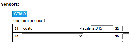
1227 / 600 = 2.045
This is not exact, as we test each CT specifically. Also, if the CT polarity is reversed on the custom CT, the scale factor will need to be negated.
Configure the CT as in the example below using your calculated scale factor:
Connection Quality
The eGauge can record network connection quality as a percentage value (0..100). This information is displayed on the Status page (http://DEVNAME.egaug.es/status.html where DEVNAME is the device name of your eGauge meter) under "Connection Quality" by default, but historical values are not stored. Storing network connection quality as a register may be useful for certain types of troubleshooting (for example, to determine if the HomePlug signal is interrupted by a certain piece of equipment turning on/off). Note that this value updates once a minute (not necessarily at the top of the minute).
For devices sold after January 1, 2024 this information can be seen at: https://DEVNAME.egauge.io/status.html where DEVNAME is the device name of your eGauge meter.
To record network connection quality:
Under Registers, click the "Add Registers" button
Name the register as appropriate
Using the dropdown menu, change the register type from "P" to "="
A second dropdown menu will appear. Select the unit type to "number"
In the formula field, enter the following: conn_qual() (note that nothing should be entered between the parentheses)
Click "Save" at the bottom of the page when finished (valid credentials required)

Sample Connection Quality register using conn_qual()
Note that this function is available on the EG30xx and EG4xxx hardware. It is not available on the eGauge2. conn_qual() tracks the connection quality of whatever network interface is in use, and does not need to be modified or adjusted if the network interface is changed (for example, if switching from HomePlug to Ethernet communication). As with all physical registers, conn_qual() will only start recording data from the time it is created.
Net import/export registers on line side tap system
On a backfed PV installation (that is, an installation where excess solar production is fed back through a breaker on the main distribution panel to the utility) it is relatively easy to see the net import and export of power. The CTs installed on the main utility feeds are in effect net CTs, as they see power imported from and exported to the utility. Any register created using those CTs will thus change polarity when production exceeds consumption, and change back when consumption exceeds production. For instructions on displaying the net import/export values for a backfed system, see this article.
However, a line side tap PV installation (where the solar is tapped between the main utility feed CTs and the utility meter itself) only tracks the consumption of the main distribution panel by default. A register using the main utility feed CTs will only see the consumption associated with that panel, regardless of how much production is being fed back to the utility. In this case, a comparison between the main utility CTs ("Grid" register) and the production CTs ("Solar" register) can show how much power is being imported or exported.
To track this information, two formula registers must be created as follows:

Figure 1: Sample Net Import/Export register setup
Net In = min($"Solar" - $"Grid",0)
Net Out = max($"Solar" - $"Grid",0)
Note that this assumes two registers, one named "Grid" which tracks only consumption on the main distribution panel, and one name "Solar" which tracks total solar production. If needed multiple registers can be combined.
A new register will not contain any historical data. There is no way to backfill historical data into a new register.
The next step is to create a new view to display the net import and net export registers properly. To do this:
1. Under "Totals and Virtual Registers", create two new virtual registers "Net.Usage" and "Net.Generation".
2. Set Net.Usage equal to "Net In", and Net.Generation to "Net Out". When done, they should look like this:
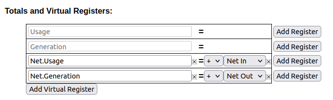 Figure 2: Virtual Register Configuration
3. Save your changes and reboot if prompted.
Once the register split process has been completed, data can be viewed on the main graph page by selecting the "Net" view. The images below show a comparison between the default "total used/total generated" graph and the new "net used/net sold" graph.
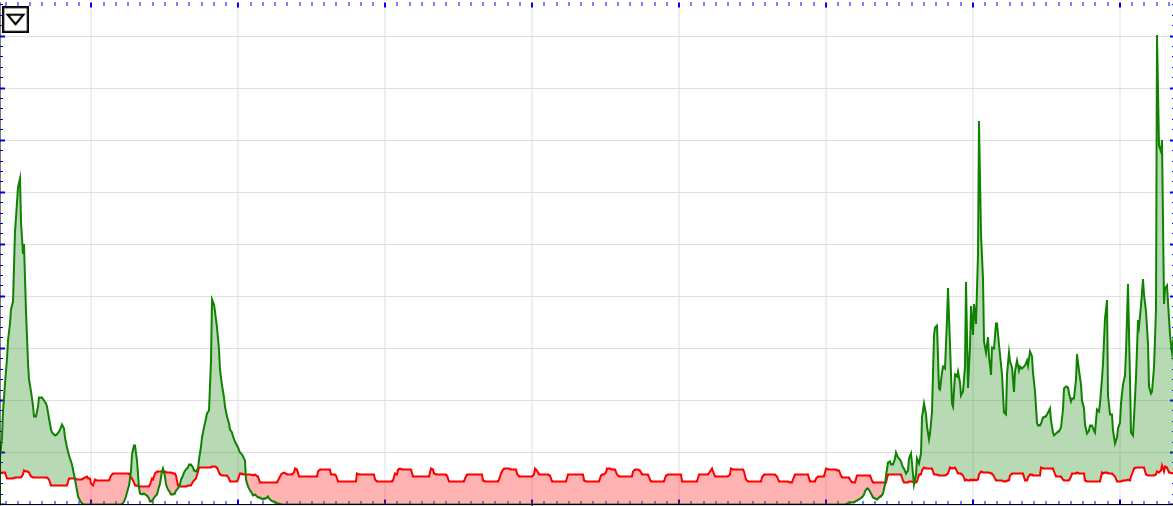
Figure 3: Default view (note overlapping Usage and Generation lines)
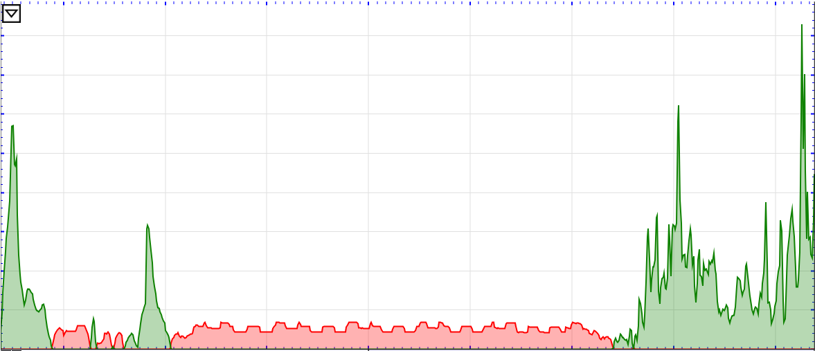 Figure 4: Net view (note power is either moving to or from the utility)
Net import/export registers on a backfed system
In some cases, it can be useful to graph the net flow of power to and from the utility, instead of the total power consumed and produced. This process adds a new view to display this information. The instructions below only apply to backfed PV systems - use these instructions for lineside tap installations.
Note that valid credentials are needed to apply these changes. These instructions also assume that these registers are being added to an existing installation. Steps 6-7 can be skipped on a fresh installation.
2. Set the "Grid" register to record both positive and net values. When done, it should look like this:

Figure 1: Grid register configuration
3. Add two new virtual registers: "Net.Usage" and "Net.Generation". Note the spelling and capitalization must match exactly.
4. Set "Net.Usage" to equal "Grid+" and "Net.Generation" to equal "Grid-". When done, they should look like this:

Figure 2: Virtual register configuration
5. Save and reboot.
6. Once the eGauge comes back online, navigate to Tools -> Split Registers.
7. Select "Grid" and click Start Splitting. This process can take 10-15 minutes - do not reboot the eGauge during this time.
Once the register split process has been completed, data can be viewed on the main graph page by selecting the "Net" view. The images below show a comparison between the default "total used/total generated" graph and the new "net used/net sold" graph.

Figure 3: Default view (note overlapping Usage and Generation lines)

Figure 4: Net view (note power is either moving to or from the utility)
Reactive Power (kVAr)
Reactive power can be recorded using a formula register.
First, create a power register for the equipment monitored:

Next, click the power sub-type selector box to the right of the "P" box:

Choose "* Record apparent power" and press OK:

Finally, add a new register, change the "P" box to an equals sign for a formula register, choose "react. power [var]" as the unit, and enter a formula of:
VAr($"registername", $"registername*") where registername is the name of the power register. Note the asterisk (*) on the end of the second register name - this references the apparent power register.

Potential Transformer Configuration
eGauge Systems cannot guarantee meter accuracy when third party potential transformers are used. It is recommended to use the EV1000 high voltage sensor when measuring a high voltage system (480V no-neutral, 347V no-neutral or 600V system), or on a different side of a transformer from where the eGauge is connected.
The eGauge AC voltage inputs can handle up to 277Vrms between any line input (L1, L2, L3) and neutral terminal. If voltages exceed this range, potential transformers must be used to step-down the voltage from the system to the eGauge voltage input terminals.
When using a potential transformer, the eGauge must be configured appropriately in Settings -> Installation -> Potential Transformers. Generic options such as 277:120 and 480:120 are available, as well as specific supported transformer models, such as FDT-480-120.
A set of negated transformer values are also available. Choosing this negates the polarity of the voltage. This has the effect of negating all power calculations using this transformer setting.
The PT ratio is configured in Settings -> Installation under the PT section. To use a custom ratio, choose "custom" and enter the scale factor:
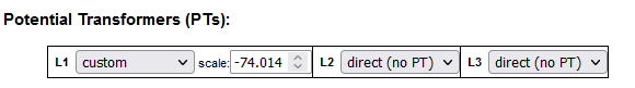
Custom potential transformer ratios
If a custom, unsupported step-down transformer ratio is used but not available in the drop-down menu, a custom scale factor will need to be used.
To calculate a custom potential transformer scale factor, use the following calculation:
secondary / primary * model_pt_value = SCALE_FACTOR
where:
| secondary | is the secondary voltage |
| primary | is the primary voltage |
| model_pt_value | is a model-specific value (see below) |
| SCALE_FACTOR | is the custom scale factor you should use on the eGauge2 and EG30xx |
The model_pt_value number will vary based on what model eGauge is in use, as described below (note values are negated):
| EG4xxx (with LCD display) | -74.0140 |
| EG30xx (no LCD, w/ Ethernet) | -4.003 |
| eGauge2 (no Ethernet, no LCD) | -4.003 |
For example:
EG4xxx with a 277:240 transformer would have a custom scale of -64.128:
240 / 277 * -74.0140 = -64.128
Similarly, an eGauge2 or EG30xx with a 277:240 transformer would have a custom scale of -3.4683:
240 / 277 * -4.003 = -3.4683
Frequency Registers
The eGauge can be set to record individual CT or line voltage frequency readings as separate registers.
Firmware 4.0 and newer
To add frequency registers:
Under Registers, click the "Add Registers" button
Name the register as appropriate
Using the dropdown menu, change the register type from "P" to "S" (for CT frequency) or "L" (for voltage tap frequency)
In the next dropdown menu, select the appropriate sensor input or voltage reference
In the final dropdown menu, select "frequency"
Click "Save" at the bottom of the page when finished (valid credentials required)

As with all physical registers, data will only start recording from the time the register is created.
Legacy (pre firmware 4.0)
Firmware versions older than 4.0 can only record frequency on line voltage measurements. To add frequency registers:
Under Registers, click the "Add Registers" button
Name the register as appropriate
Using the dropdown menu, change the register type from "P" to "F"
A second dropdown menu will appear. Select the appropriate voltage reference
Click "Save" at the bottom of the page when finished (valid credentials required)
As with all physical registers, data will only start recording from the time the register is created.