eGauge Meter Communication
Covers meter communication options, including Modbus TCP/RTU, BACnet, and remote eGauge meters.
- JSON WebAPI
- Introduction
- Firmware Versions and API Access
- Authentication
- Register Data Examples
- Technical Documentation
- XML API
- Interpreting XML data and examples
- XML API
- Timezone and "Z" parameter
- Authentication (HTTP Digest Authentication)
- Modbus
- Modbus Output Communication
- Sunspec Support
- Custom Modbus definitions (read from any Modbus device)
- Creating, Sharing, and Using Modbus Maps
- BACnet
- Serial and USB485
- Displaying the Manage Router option on Samsung mobile devices
- HomePlug power-line communication
- What do the different LEDs on the HomePlug adapter mean?
- Can the HomePlug adapter be connected to a power strip?
- HomePlug Security Considerations
- How do I pair the eGauge with a HomePlug adapter?
- What are some causes of HomePlug communication issues?
- How do I check HomePlug communication speed?
- EG42xx Wifi Connection
- Network Connections
- eGauge Proxy Server Security and Functionality
- Configuring a remote eGauge
- Configuring a USB WiFi dongle
- Comparison of Communication Options
- Custom HTTPS certificates (EG4xxx only)
- eGauge.io Service
- Unix time, timestamps, and timezone information
JSON WebAPI
Information about the eGauge meter's JSON-based API
Introduction
The WebAPI documentation may be found at egauge.net/support/webapi.
The Web API was introduced in firmware v.4.2, however eGauge Systems periodically releases new firmware versions with bug fixes, enhancements, and new features to the WebAPI. It is recommended to use the latest eGauge firmware version. Click here for information about checking and upgrading eGauge meter firmware.
Be sure to select the appropriate firmware version in the WebAPI documentation for your meter in the upper left-hand corner of the documentation system. By default, the WebAPI documentation defaults to information about the latest stable firmware release.
The eGauge WebAPI is a JSON-based API framework that allows for automated meter configuration, recorded data retrieval, status information, and more.eGauge Systems provides a Python library to assist with authentication and other interactions with the eGauge meter WebAPI and can be installed from from PyPi (pip) or Bitbucket (source code) .
Getting Started With Python
To make it easy to get started, eGauge provides an open source Python package. It can be installed with the command:
pip install egauge-python
With this package installed, accessing an eGauge meter becomes very simple. For example, to fetch the hostname of the meter, you could use:
from egauge import webapi
URI = "https://DEV.egaug.es" # replace DEV with meter name
USR = "USER" # replace USER with user name
PWD = "PASS" # replace PASS with password
dev = webapi.device.Device(URI, webapi.JWTAuth(USR,PWD))
print("hostname is " + dev.get("/config/net/hostname")["result"])
The package also contains various convenience classes to read meter data, capture waveform samples, convert between physical units, and so on.
The official GIT repository for this package is at https://bitbucket.org/egauge/python/. Various code examples can be found in the examples directory.
Getting started without the eGauge Python library
Check out the support library page on WebAPI Authentication for examples on authentication.
Common WebAPI service descriptions
See the WebAPI documentation for full details and all service endpoints available. The endpoints below are only several commonly accessed endpoints that retrieve data and configuration.
/auth
Service used to obtain or invalidate a JSON web token used for authenticating with the WebAPI.
/config
The /config service allows you to read and write configuration to the meter.
/register
The /register service provides instantanoues and historical register data that is recorded
on the meter.
/local
The /local service provides instantaneous information derived from configured channel inputs,
including RMS value, mean value, frequency value and instantanoues power and energy values if
power registers are configured.
For historical or newly generated register data, use the /register service.
Other WebAPI service descriptions
Below are the additional service endpoints not listed above. See the WebAPI documentation for full details and all service endpoints available.
/capture
The /capture service is used for obtaining raw waveform data from the inputs. To obtain normal
RMS, mean or frequency from the sensors directly, use the /local service. For obtaining stored or
newly generated register data, use the /register service.
/cmd
Service used to send commands to the meter such as reboot or firmware upgrade.
/ctid
Service used to read or configure CTid sensors from a meter or flash the LED on the sensor (EG4xxx only).
/ctrl
Service used for controlling supported remote devices, such as the PRM3 relay module.
/log
Service used to access syslog or kernel logs. Syslog must be enabled through the /config service
endpoint first.
/lua
Service used for managing Lua scripts on the meter.
/providers
Service used for obtaining information about third-party providers that support meter services such as push data sharing, push alerts, and tariffs.
/store
Service used for storing and retrieving preferences and other settings typically used in the user's web browser interface.
/remote
Service used for configuring remote devices on the meter.
/sys
Service used to obtain system information such as firmware version, uptime, serial number, meter model, and more.
Firmware Versions and API Access
Firmware versions and relase notes may be found at egauge.net/revs
Minimum firmware version
The eGauge JSON-based WebAPI was introduced in meter firmware v4.2. However, it is recommended to use the most recent meter firmware as there have been multiple bug fixes and features added, as there may continue to be in the future.
Checking and upgrading firmware
Meter firmware upgrades are designed to be easy and require just a few mouse clicks, no searching for model numbers or having to download files or software! For information about checking and upgrading the meter's firmware, please see this article.
Changing WebAPI documentation version
The WebAPI documentation is version-controlled and older versions of the WebAPI documentation can be viewed by changing the version selector in the upper left-hand corner of the WebAPI documentation page:
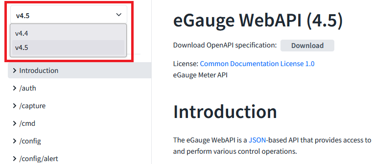
This, for example, allows you to see only the API endpoints and features available in a given firmware. If the specific firmware version documentation does not exist, choose the closest lower-numbered release. For example, if the meter firmware is v4.4.2, the correct documentation version in the screenshot is v4.4.
However, it is recommended to use the latest meter firmware release as there may be periodic bug fixes and improvements.
Authentication
View the /auth section information in the WebAPI documentation
for full details on the authentication methods of the eGauge meter WebAPI.
The eGauge WebAPI uses JSON web token (JWT) authentication for all interactions. An "Authorization"
header must be provided with WebAPI requests in the format of Authorization: Bearer JWT where
JWT is a valid JSON web token.
Tokens typically expire after 10 minutes and need to be renewed periodically.
There are two methods to obtaining a token:
- Digest Object. This is the recommended method for obtaining a JWT and is described in this document. This method is similar to the HTTP Digest authentication method.
- Password Object. This method sends the credentials as plaintext, and therefore requires a secure connection, e.g., HTTPS to the local IP address of the meter. This method will return an error if attempted over the eGauge proxy server, even if HTTPS is used.
You may find more information about the authentication methods by clicking the object you wish
to use in the WebAPI documentation /auth section:

Digest Authentication workflow
-
Send a GET to /auth/unauthorized to get a 401 to get the realm (
rlm) and server nonce (nnc) -
Generate a client nonce (
cnnc) -
Calculate
hashin the format:ha1 = MD5(usr:rlm:pwd)
hash = MD5(ha1:nnc:cnnc)
whereusrandpwdare a valid user and password on the meter -
Send
rlm,usr,nnc,cnncandhashto /auth/login for the token
Digest Authentication in Python
eGauge Systems provides a Python library with helper functions to deal with authentication and other interactions. See the WebAPI introduction page for more information.
#!/usr/bin/env python3
# Example Python script obtaining a JSON web token (JWT) from a meter's WebAPI.
# JWTs are needed for any interactions with the meter's JSON-based WebAPI.
# eGauge provides a Python library that handles authentication automatically and
# provides additional helper functions. It may be found on Bitbucket or PyPi
# https://bitbucket.org/egauge/python/src/master/egauge/
# https://pypi.org/project/egauge-python/
# Main WebAPI documentation: https://egauge.net/support/webapi
import requests
import hashlib
from secrets import token_hex
# meter and credential information
URI = "https://eGauge67385.d.egauge.net"
USER = "admin"
PASS = "as$kS2345da2@4vK9"
# get realm (rlm) and server nonce (nnc):
auth_req = requests.get(f"{URI}/api/auth/unauthorized").json()
realm = auth_req["rlm"]
nnc = auth_req["nnc"]
cnnc = str(token_hex(64)) # generate a client nonce (cnnc)
# generate our hash
# ha1 = MD5(usr:rlm:pwd)
# hash = MD5(ha1:nnc:cnnc)
ha1_content = f"{USER}:{realm}:{PASS}"
ha1 = hashlib.md5(ha1_content.encode("utf-8")).hexdigest()
hash_content = f"{ha1}:{nnc}:{cnnc}"
hash = hashlib.md5(hash_content.encode("utf-8")).hexdigest()
# Generate our payload
payload = {
"rlm": realm,
"usr": USER,
"nnc": nnc,
"cnnc": cnnc,
"hash": hash
}
# POST to /auth/login to get a JWT
auth_login = requests.post(f"{URI}/api/auth/login", json=payload).json()
rights = auth_login["rights"] # rights this token has (save, control, etc)
jwt = auth_login["jwt"] # the actual bearer token
print(f"Got token with rights {rights}.")
# We can verify this token works.
# Add an authorization header with our token and make a request
headers = {"Authorization": f"Bearer {jwt}"}
api_request = requests.get(
f"{URI}/api/config/net/hostname",
headers=headers,
)
# {'result': 'eGauge67385'}
print(api_request.json())
# This token may be used until it expires, in which case a 401 response will be
# returned, to which this process can be reperformed.
Digest Authentication with Bash
This bash script uses curl and jq to obtain a JWT for use with the WebAPI.
URI="https://eGauge67385.d.egauge.net"
USER="admin"
PASS="as$kS2345da2@4vK9"
auth_req=$(curl -s "$URI/api/auth/unauthorized")
rlm=$(jq -r '.rlm' <<< $auth_req)
nnc=$(jq -r '.nnc' <<< $auth_req)
cnnc=$(openssl rand -hex 64)
ha1=$(echo -n "$USER:$rlm:$PASS" | md5sum | cut -f1 -d" ")
hash=$(echo -n "$ha1:$nnc:$cnnc" | md5sum | cut -f1 -d" ")
auth_login=$(curl -s -X POST "$URI/api/auth/login" \
-H "Content-Type: application/json" \
-d "{\"rlm\": \"$rlm\", \"usr\": \"$USER\", \"nnc\": \"$nnc\", \"cnnc\": \"$cnnc\", \"hash\": \"$hash\"}")
jwt=$(jq -r '.jwt' <<< $auth_login)
api_request=$(curl -s "$URI/api/config/net/hostname" -H "Authorization: Bearer $jwt")
echo $api_request
Register Data Examples
This page contains a few basic examples of obtaining historical register data from an eGauge meter using the WebAPI.
These examples use the eGauge Python library but other languages and libraries may be used.
Get Instantaneous values
Request: dev.get('/register?reg=3+5+7+9&rate')
Parameters:
reg=3+5+7+9 asks for those register IDs
rate asks for the instantaneous rate of change at the time
No time parameter was provided, so it gets the latest value
Response:
{
"ts": "1679506470.000420096",
"registers": [
{"name": "Panel 3 Mains", "type": "P", "idx": 3, "did": 0, "rate": 2400},
{"name": "Panel 3 L1", "type": "P", "idx": 5, "did": 2, "rate": 551},
{"name": "Panel 3 L2", "type": "P", "idx": 7, "did": 3, "rate": 1080},
{"name": "Panel 3 L3", "type": "P", "idx": 9, "did": 4, "rate": 769},
],
}
Get 6 hour period of historical data
Request: dev.get('/register?reg=3+5+7+9&rate&time=1672556400:3600:1672578000')
Parameters:
reg=3+5+7+9 asks for those register IDs
rate asks for the instantaneous rate of change at the time
time=1672556400:3600:1672578000 is:
-
1672556400: Jan 1 12:00AM (start time) -
3600: number of seconds to skip between rows (makes 1 hour granularity) -
1672578000: Jan 2 6:00AM (end time)
Response:
{
"ts": "1679505959.000420096",
"registers": [
{"name": "Panel 3 Mains", "type": "P", "idx": 3, "did": 0, "rate": 4185},
{"name": "Panel 3 L1", "type": "P", "idx": 5, "did": 2, "rate": 506},
{"name": "Panel 3 L2", "type": "P", "idx": 7, "did": 3, "rate": 2902},
{"name": "Panel 3 L3", "type": "P", "idx": 9, "did": 4, "rate": 777},
],
"ranges": [
{
"ts": "1672578000",
"delta": 3600.0,
"rows": [
["150555067851", "64158660544", "57705425071", "28690982234"],
["150552980706", "64157713471", "57704901028", "28690366205"],
["150550413006", "64156764160", "57703892567", "28689756277"],
["150548310776", "64155810457", "57703366875", "28689133443"],
["150546201980", "64154853051", "57702841741", "28688507186"],
["150543949276", "64153896433", "57702279596", "28687773245"],
["150541826993", "64152938219", "57701751003", "28687137769"],
],
}
],
}
Notes
Parse output the same way that would be done for XML data.
Each row is delta seconds (3600) older than the previous row. The columns are in order of the registers, that is the first value in each row is for "Panel 3 Mains", the second value in each row is for "Panel 3 L1", and so on.
Row 1:
150555067851 is the cumulative value of "Panel 3 Mains" at time "ts" (1672578000 = Jan 1 6:00AM)
64158660544 is the cumulative value of "Panel 3 L1" at time "ts" (1672578000 = Jan 1 6:00AM)
57705425071 is the cumulative value of "Panel 3 L2" at time "ts" (1672578000 = Jan 1 6:00AM)
Row 2:
150552980706 is the cumulative value of "Panel 3 Mains" at time "ts"-"delta"*1 (1672578000-3600*1 = Jan 1 5:00AM)
Row 3:
150550413006 is the cumulative value of "Panel 3 Mains" at time "ts"-"delta"*2 (1672578000-3600*2 = Jan 1 4:00AM)
Row 4:
150548310776 is the cumulative value of "Panel 3 Mains" at time "ts"-"delta"*3 (1672578000-3600*3 = Jan 1 3:00AM)
Row 7:
28687137769 is the cumulative value of "Panel 3 L3" at time "ts"-"delta"*6 (1672578000-3600*6 = Jan 1 12:00AM)
For example, "Panel 3 Mains", between 12:00AM and 6:00AM on Jan 1 used (150555067851-150541826993)/3,600,000 == 3.679 kWh
Get 3 particular timestamps
Request: dev.get('/register?reg=3:5&time=1672556400,1672642800,1672729200')
Parameters:
reg=3:5 asks for registers starting at ID 3 and ending at ID 5
time=1672556400,1672642800,1672729200 requests the values at timestamps of:
-
1672556400: Jan 1 12:00AM -
1672642800: Jan 2 12:00AM -
1672729200: Jan 3 12:00AM
Response:
{
"ts": "1679507855.000420096",
"registers": [
{"name": "Panel 3 Mains", "type": "P", "idx": 3, "did": 0},
{"name": "Panel 3 Mains*", "type": "S", "idx": 4, "did": 1},
{"name": "Panel 3 L1", "type": "P", "idx": 5, "did": 2},
],
"ranges": [
{
"ts": "1672556400",
"delta": 60.0,
"rows": [["150541826993", "182491473811", "64152938219"]],
},
{
"ts": "1672642800",
"delta": 60.0,
"rows": [["150591166950", "182556552340", "64175776009"]],
},
{
"ts": "1672729200",
"delta": 60.0,
"rows": [["150704245365", "182691087288", "64205578174"]],
},
],
}
Notes
Parse the same as XML output. There are 3 ranges, one for each of the requested timestamps, and each register's cumulative value at that time.
For example:
The last range shows on January 1 ("ts" of 1672729200) that "Panel 3 L1*" (middle column) had a cumulative value of 64205578174 watt-seconds.
The second to last range shows on January 2 ("ts" of 1672642800) that "Panel 3 L1*" (middle column) had a cumulative value of 64175776009 watt-seconds.
This means between January 1 and January 2, the "Panel L1" register changed by (64175776009-64205578174) = -29802165 watt-seconds, which is -29802165/3600000 = -8.27 kWh
Depending on the orientation of the amperage sensor (CT), the power/energy will register as positive or negative. If there is unidirectional power (no back-feeding, etc.) it is usually safe to take the absolute value between dates. However, unexpected power polarity can also be caused by physical installation issues that are generating innacurate data.
Technical Documentation
The latest eGauge meter WebAPI documentation may be found at egauge.net/support/webapi
XML API
eGauge has a free XML-format API for requesting data
Interpreting XML data and examples
Contained in this article:
General Information
XML data is sent with cumulative register values. In the case for power registers, the cumulative values are in watt-seconds. To convert watt-seconds to kWh, divide the watt-seconds by 3,600,000. Cumulative values can be imagined as meter readings at that point in time, where consumption readings continuously increase over time. To get the kWh usage between two dates, subtract the more recent value from the older value and divide by 3,600,000.
EG4xxx meters support TLSv1.2, while EG30xx only supports TLSv1.0
At the bottom of the page is the output of a minute granular export showing the past ten minutes of cumulative data (obtained with the URL http://DEVNAME.egaug.es/cgi-bin/egauge-show?m&n=10). time_stamp represents the time of the export (unix timestamp in hex); time_delta indicates the time in seconds between exports; epoch represents the date and time recording started on that device (unix timestamp in hex).
Each <cname> tag contains data on a column header; in this case, that translates to a physical register on the device. t indicates the register type (P for power, V for Voltage, etc) and the text inside the tag represents the register name as recorded on the device. Virtual registers may also be shows in the appropriate parameter is passed in the initial request.
Each row (<r> tag) contains a series of columns (<c> tag) that show the cumulative value of each register. To determine the average value of a register over a given time, simply find the difference between the two cumulative values and divide by the appropriate time delta. The resulting values are expressed in units based on the register type (see the chart in section 2.2.1 of the XML API document for the unit type). It should be noted that prior to firmware 3.01 cumulative values do not necessarily count up from zero. On firmware 3.01 and newer passing the option E when requesting data returns values relative to device epoch (ie, values start at zero). Using the parameter epoch in a data push has the same effect. This assumes that the date and time recording started option is set correctly on the eGauge.
Some examples (based on the sample output below):
Average Grid usage over the most recent minute 55357226851 - 55357243343 = −16492 / 60 = -274.86 Watts (remember, Power registers are bidirectional)
Average Voltage L2 over ten minutes 4511385868513 - 4511319123106 = 66745407 / 600 = 111242.345 mV / 1000 = 111.24 Volts
<group serial="0x4e842294"> <data columns="12" time_stamp="0x564cb0e8" time_delta="60" epoch="0x55973268"> <cname t="P">Grid</cname> <cname t="S">Grid*</cname> <cname t="V">VL2</cname> <cname t="V">VL1</cname> <cname t="F">Frequency</cname> <r> <c>55357226851</c> <c>7375247726</c> <c>4511385868513</c> <c>4528987513211</c> <c>2217532746128</c> </r> <r> <c>55357243343</c> <c>7375223338</c> <c>4511378482617</c> <c>4528980146863</c> <c>2217529147760</c> </r> <r> <c>55357259861</c> <c>7375198952</c> <c>4511371100578</c> <c>4528972784417</c> <c>2217525549473</c> </r> <r> <c>55357276431</c> <c>7375174516</c> <c>4511363715094</c> <c>4528965418400</c> <c>2217521950920</c> </r> <r> <c>55357293137</c> <c>7375149735</c> <c>4511356276347</c> <c>4528957999802</c> <c>2217518352640</c> </r> <r> <c>55357309872</c> <c>7375124940</c> <c>4511348838707</c> <c>4528950580365</c> <c>2217514754150</c> </r> <r> <c>55357326630</c> <c>7375100152</c> <c>4511341406162</c> <c>4528943162279</c> <c>2217511155334</c> </r> <r> <c>55357343410</c> <c>7375075359</c> <c>4511333976595</c> <c>4528935743683</c> <c>2217507556120</c> </r> <r> <c>55357360207</c> <c>7375050569</c> <c>4511326550844</c> <c>4528928327670</c> <c>2217503956798</c> </r> <r> <c>55357377048</c> <c>7375025739</c> <c>4511319123106</c> <c>4528920909766</c> <c>2217500357151</c> </r> </data> </group>
Example: Energy and power for specific dates
You can make CGI calls to http://DEV-URL/cgi-bin/egauge-show where DEV-URL is the URL of your eGauge (for example, http://egaugehq.d.egauge.net/).
The T parameter lets you request data from specific points in time. It expects a comma separated list of Unix time-stamps.
The E parameter requests the values be relative to the Date and Time when recording started. This needs to be set correctly in Settings -> Date & time when recording started. It effectively makes the reading start at zero when the date and time when recording started is set to, otherwise the raw database value could be arbitrary. This requires firmware v3.02 or greater.
The a parameter requests total and virtual registers, such as "Usage" and "Generation". This is optional.
http://egaugehq.d.egauge.net/cgi-bin/egauge-show?a&E&T=1514764800,1483228800 returns data for January 1 2018 00:00:00 UTC, and January 1 2017 00:00:00 UTC respectively, using epoch-relative values and requesting total and virtual registers. The output below has all the other registers except for Usage and Generation removed for readability.
<group serial="0x3b2d1cb7">
<data columns="27" time_stamp="0x5a497a00" time_delta="60" epoch="0x52a0f760">
<cname t="P">use</cname>
<cname t="P">gen</cname>
<r>
<c>241517238757</c>
<c>0</c>
</r>
</data>
<data time_stamp="0x58684680" time_delta="900">
<r>
<c>171138633823</c>
<c>0</c>
</r>
</data>
</group>
Generation is zero because there is none recorded on this device.
Usage for timestamp 0x5a497a00 (Jan 1 2018) is 241517238757 joules (241517238757/3600000 = 67088 kWh).
Usage for timestamp 0x58684680 (Jan 1 2017) is 171138633823 joules (171138633823/3600000 = 47538 kWh).
If you want power instead of energy, subtract the values and divide by the amount of time between them:
67088 kWh - 47538 kWh = 19550 kWh were used between 2017 and 2018. 1 year is 8760 hours, so 19550 kWh / 8760 h = 2.23 kW average over the year. This can be done using any two points in time.
Another description example:

XML API
eGauge Systems offers access to a free, unrestricted API for use in developing applications which fetch data from the eGauge meter. This API covers the same functions used by the default eGauge interface. The eGauge push service functionality is also covered in the API.
eGauge technical support can offer assistance interpreting XML data. Code review and similar support is not available.
EG4xxx meters support TLSv1.2, while EG30xx only supports TLSv1.0
|
|

Timezone and "Z" parameter
The "Z" parameter and timezone information is only used in the XML API when exporting in CSV format. This only affects human-friendly Date & Time values in CSV exports. It does not have any affect when returning XML formatted data, nor any affect on any time-related input parameters.
Beginning in firmware v1.2, omitting the value of the "Z" parameter will cause the CSV output to use the locally configured timezone for human-friendly CSV Date & Time values (configured in Settings -> Date & Time). For this to work, the "Z" parameter must be passed, but with an empty value (e.g., egauge-show?n=60&m&c&Z=)
When using the XML API to request data in CSV format, the query string parameter "Z" is used to specify a timezone to format the Date & Time column in the CSV output. Omitting this parameter completely will cause the Date & Time column to output Unix Timestamps. Providing an invalid value is undefined, but may cause the Date & Time to output in UTC time in human-friendly format.
The format of this string is described under the environment variable TZ at https://pubs.opengroup.org/onlinepubs/009695399/basedefs/xbd_chap08.html. Examples of how to decode and write custom timezones can be found at the end of this page.
Common Timezones
| US/Eastern | LST5LDT4,M3.2.0/02:00,M11.1.0/02:00 |
| US/Central | LST6LDT5,M3.2.0/02:00,M11.1.0/02:00 |
| US/Mountain | LST7LDT6,M3.2.0/02:00,M11.1.0/02:00 |
| US/Arizona | LST7 |
| US/Pacific | LST8LDT7,M3.2.0/02:00,M11.1.0/02:00 |
| US/Alaska | LST9LDT8,M3.2.0/02:00,M11.1.0/02:00 |
| US/Hawaii | LST10 |
| US/Baker Island | LST-12 |
| US/Samoa | LST11 |
| Australia/Central | LST-10:30 |
| Australia/Eastern | LST-10LDT-11,M10.1.0/02:00,M4.1.0/03:00 |
| Australia/Norfolk | LST-12:30 |
| Azores Islands | LST1LDT0,M3.5.6/24:00,M10.5.0/01:00 |
| Brazil | LST3LDT2,M10.3.6/24:00,M2.5.6/24:00 |
| Canada/Atlantic | LST4LDT3,M3.2.0/02:00,M11.1.0/02:00 |
| China/Beijing | LST-8 |
| Europe/Central | LST-1LDT-2,M3.5.0/02:00,M10.5.0/03:00 |
| Europe/Eastern | LST-2LDT-3,M3.5.0/03:00,M10.5.0/04:00 |
| Europe/Western | LST0LDT-1,M3.5.0/01:00,M10.5.0/02:00 |
| India | LST-6:30 |
| Iran | LST-4:30LDT-5:30,M3.3.2/24:00,M9.3.4/24:00 |
| Iraq/Baghdad | LST-3 |
| Kazakhstan/Astana | LST-6 |
| New Zealand | LST-12LDT-13,M9.5.0/02:00,M4.1.0/03:00 |
| Pakistan/Karachi | LST-5 |
| Russia/Moscow | LST-4 |
| Russia/Vladivostok | LST-11 |
| South Sandwich | LST2 |
| Thailand/Bangkok | LST-7 |
| Tokyo | LST-9 |
Decoding and understanding timezone strings
In the timezone strings, "LST" and "DST" stand for "Local Standard Time" and "Daylight Standard Time", respectively.
For a full description of the timezone string format, see the environment variable TZ at https://pubs.opengroup.org/onlinepubs/009695399/basedefs/xbd_chap08.html.
The string is generally divided into 3 sections separated by commas. The first section describes the difference between UTC and local times. The second section describes when daylight time begins, and the third section describes when it ends.
The sections describing when daylight savings starts and ends is in the following format:
Mm.n.d/t
The d'th day (0 <= d <= 6) of week n of month m of the year (1 <= n <= 5, 1 <= m <= 12, where week 5 means "the last d day in month m" which may occur in either the fourth or the fifth week). Week 1 is the first week in which the d'th day occurs. Day zero is Sunday. t is the 24-hour time in which it occurs. If omitted, it defaults to 2:00 AM.
US/Eastern
Timezone string: LST5LDT4,M3.2.0/02:00,M11.1.0/02:00
Each section, separated by commas, is described as such:
LST5LDT4UTC is 5 hours after local standard time (LST5), and UTC is 4 hours after daylight savings time (LDT4)M3.2.0/02:00Daylight Saving Time starts in March (3) on the second week (2) on Sunday (0) at 2:00AM (2:00)-
M11.1.0/02:00Daylight Savings Time ends in November (11) on the first week (1) on Sunday (0) at 2:00AM (2:00)
US/Hawaii
Timezone string: LST10
UTC is 10 hours after local Hawaii time. Daylight savings time is not observed, so there is no LDT definition or additional sections.
New Zealand
Timezone string: LST-12LDT-13,M9.5.0/02:00,M4.1.0/03:00
Each section, separated by commas, is described as such:
LST-12LDT-13UTC is 12 hours earlier than local standard time (LST-12), and UTC is 13 hours earlier than local daylight time (LDT-13)M9.5.0/02:00Daylight Saving Time starts in September (9) on the last week (5) on Sunday (0) at 2:00AM (2:00)M4.1.0/03:00Daylight Savings Time ends in April (4) on the first week (1) on Sunday (0) at 3:00AM (3:00)
Authentication (HTTP Digest Authentication)
If the eGauge meter is set with site-wide password authentication, all resources will require HTTP Digest Authentication. Many programming languages and libraries have support for HTTP Digest Authentication, so well maintained and trusted libraries for HTTP Digest Authentication are preferable to use over custom implementations. In the event there is no existing support for HTTP Digest Authentication, it can be manually implemented. eGauge Systems cannot provide assistance on this implementation.
Wikipedia has information and examples of how to perform Digest Authentication and what header values must be returned. Note, any protected resources under the XML API will use a "quality of protection" (qop) of "auth", which will affect how the header values are calculated using HTTP Digest Authentication.
The basic steps to perform HTTP Digest Authentication are:
- Make an unauthenticated request to the resource you wish to access.
- Look at the WWW-Authentication header returned. Store the following values:
Digest realm(realm space of protected resource. Generally this is "eGauge Administration" unless the interface is custom-branded)nonce(server nonce, changes for each unauthenticated request)qop(always will be "auth" for the eGauge XML API) - Perform the following calculations:
HA1 = MD5(username:realm:password)HA2 = MD5(method:digestURI)(note the digestURI is the path of the resource, not including host or FQDN. E.g., /cgi-bin/egauge-show)response = MD5(HA1:nonce:nonceCount:cnonce:qop:HA2)(nonceCount may be "1" for the initial request. cnonce
is a nonce generated by the client, such as a 64 bit hexadecimal value) - Send a request to the same URI in step 1, and this time include an "Authorization" header with the following parameters and values:
Digest username= username for authenticationrealm= realm (from step 2)nonce= server nonce (from step 2)uri= request uri (used in HA2 in step 3)response= response (generated in step 3)qop= "auth"nc= nonce count (can simply be "1" for testing, should be incremented for subsequent requests that reuse the same nonce)cnonce= client nonce generated in step 3
It is not always necessary to perform step 2 in this process if making repeated requests to the same resource (URI or "digestURI"). A server nonce expire after 10 minutes and attempting to re-use will result in a 401 with WWW-Authenticate header like found in step 1, with a "stale=true" parameter in the header string.
Modbus
eGauge meters can read and output Modbus RTU and TCP
Modbus Output Communication
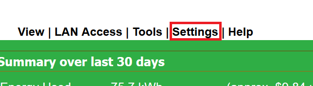
All eGauge models with firmware v3.2 or higher have Modbus TCP output capability. eGauge models with USB ports also have capability for Modbus RTU (serial via RS485) output capability, with use of the eGauge USB485 converter. The Modbus server can be enabled in Settings -> Modbus Server. If the Modbus Server option is not available, upgrade your firmware in Tools -> Firmware Upgrade.
NOTICE: Prior to firmware v4.0, the Modbus map addresses are liable to change if the register name or contents is modified. Firmware v4.0 adds additional ranges that are tied to the register ID. The addresses used prior to v4.0 are still usable to provide backwards-compatibility, but are marked as deprecated and are not recommended to use as installation settings reconfiguration may change them. Virtual registers are in the order they appear on the settings page, meaning addresses can change if virtual registers are added or deleted.
Enabling the Modbus server
In the eGauge interface, navigate to Settings -> Modbus Server. The following options are available:
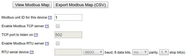
Check the box for "Enable Modbus" for the appropriate service (Modbus TCP uses Ethernet, Modbus RTU uses the eGauge USB485 serial converter).
For Modbus TCP, choose the port to listen on (default: 502).
For Modbus RTU, click inside the serial device box and detected adapters will be listed to choose from as shown below. Choose the appropriate baud rate, parity and stop bits to match the Modbus master.

Modbus Register Map
The exact Modbus map depends on the eGauge device configuration and is available on the Modbus settings screen. The map is available for viewing in the web browser or for download as a comma-separated value (CSV) file which can then be imported into any spreadsheet program.
|
Address range |
Description |
|
Timestamps |
|
|
30000 -- 30003 |
local timestamp (for use when reading from addresses <35000) |
|
30004 -- 30007 |
THD timestamp indicates when data was acquired that is used by FFTarg(), FFTarg2(), FFTmag(), and THD() functions |
|
30008 -- 30009 |
register timestamp (for use when reading from addresses ≥35000) |
|
Local data (channel checker) |
|
|
30500 -- 30999 |
Line voltages (RMS) |
|
31000 -- 31499 |
Line voltages (DC/mean) |
|
31500 -- 31999 |
Line frequencies |
|
32000 -- 32499 |
Sensor values (normal/RMS) |
|
32500 -- 32999 |
Sensor values (mean/DC) |
|
33000 -- 33949 |
Sensor frequencies |
|
Register Data [v4.0 and greater] |
|
|
34000 -- 34999 |
Reduced precision cumulative physical register values (float) |
| 35000 -- 35999
|
Cumulative virtual register values (signed 64-bit integers) |
| 36000 -- 36999 |
Change of virtual register value (float) |
| 37000 -- 37999 | Reduced precision cumulative virtual register values (float) |
| 38000 -- 38999 | Cumulative physical register values (signed 64-bit integers) |
| 39000 -- 39999 | Change of physical register value (float) |
|
Register Data [PRIOR to firmware v4.0, now deprecated] |
|
|---|---|
|
35000 -- 35999 |
Cumulative register values (signed 64-bit integers) [DEPRECATED] |
|
36000 -- 36999 |
Change of register value (float) [DEPRECATED] |
|
37000 -- 37999 |
Reduced precision cumulative register values (float) [DEPRECATED] |
In v4.0 or greater, the Modbus addresses are tied to the eGauge register IDs. They can be calculated as:
Physical float cumulative value = 34000+(ID*2)
Physical s64 cumulative value = 38000+(ID*4)
Physical float instant value = 39000+(ID*2)
Virtual registers are in the order they appear on the installation settings page, and are therefore liable to shift during deletions or additions.
The register ID can be found by hovering over the register delete button in the Installation Settings page:

An example Modbus map, which can be found in Settings -> Modbus Server, is displayed below:


The t16 type Modbus registers are variable-length UTF-8 strings and therefore multiple registers may need to be read until a UTF-8 null character is reached.
Example Modbus Transmissions:
Example Modbus TCP request and response for L1 RMS voltage:
Request: [00 01] [00 00] [00 06] [01] [04] [01 f4] [00 02]
[00 01] = Transaction identifier
[00 00] = Protocol identifier (always 00 00)
[00 06] = Bytes following (0x0006 = 6 bytes)
[01] = Unit ID
[04] = Function code (0x04 is read input registers)
[01 f4] = Starting register address (500)
[00 02] = Number of words to return (2 words for float value)
Response: [00 01] [00 00] [00 07] [01] [04] [04] [42 f6 2a 06]
[00 01] = Transaction identifier
[00 00] = Protocol identifier (always 00 00)
[00 07] = Bytes following (0x0007 = 7 bytes)
[01] = Unit ID
[04] = Function code (0x04 is read input registers)
[42 f6 2a 06] = Contents of register 500 and 501 respectively
0x42f62a06 decoded as big-endian (ABCD) float is roughly 123.08, so L1 voltage is 123.08Vrms
Example Modbus RTU request and response for L1 RMS voltage:
Request: [01] [04] [01 f4] [00 02] [31 c5]
[01] = Unit ID
[04] = Function code (0x04 is read input registers)
[01 f4] = Starting register address (500)
[31 c5] = CRC error check
Response: [01] [04] [04] [42 f6 2a 06] [90 ac]
[01] = Unit ID
[04] = Function code (0x04 is read input registers)
[04] = Data bytes to follow (not including CRC)
[42 f6 2a 06] = Contents of register 500 and 501 respectively
0x42f62a06 decoded as big-endian (ABCD) float is roughly 123.08, so L1 voltage is 123.08Vrms
Additional technical information
The maximum Modbus frame size is 255 bytes. This translates to (61) 32-bit registers or (30) 64-bit registers. Most DAS and Modbus systems will automatically split any requests to limit the response size to not exceed the upper limit. If requesting more registers than can be returned in a single frame, the response may be truncated or an exception may be returned.
Additional help is available by clicking the [?] buttons on the Modbus Server settings page.
All data is provided as Modbus input registers and therefore their Modbus addresses start at 30000. The raw frame sent does not include the prefixed '30', this indicates the function code used.
For each register recorded by eGauge, the register's current cumulative value and the amount by which it changed since the previous one-second interval can be read. The cumulative value is available with full resolution as a signed 64-bit value. For convenience, the same value is also available, at reduced resolution, as a 32-bit floating point number. The change-in-value is available only as a 32-bit floating point number. In addition to the register data, it is also possible to read locally measured data such as line-voltages, frequencies, and the value measured by each sensor-port.
The Modbus server guarantees that any data read with a single request is consistent. Timestamps are provided as a means to ensure consistency when data is read with multiple requests (e.g., to read multiple, discontiguous registers). This is accomplished by (i) reading the timestamp, (ii) performing the desired read requests, and (iii) reading the timestamp again. If the two timestamp values are the same, then reader can be certain that the data is consistent.
Sunspec Support
Sunspec is a communication standard used by many types of devices (including inverters). It is intended to ease configuration when working with hardware from different manufacturers by providing common addressing block for different device types and allowing devices to query for applicable address blocks. Essentially, Sunspec allows a Modbus master (such as the eGauge) the ability to read the list of available registers from a device, eliminating the need to create inline definitions manually.
It's fairly easy to configure a Sunspec remote device:
1. Create a new remote device entry.
2. Name the entry (names are arbitrary but should make sense to the user).
3. Select the appropriate protocol. "Serial" for Modbus RTU, and "Modbus TCP" for Modbus TCP.
4. Enter the device address. This is in the form "modbus://sunspec.<id>@<addr>" where <id> is replaced with the Modbus slave address of the remote device and <addr> is replaced with the address of the remote device.
4a. With Modbus RTU, the address will be a USB port (USB1 or USB2) along with serial settings in the form ": baud / databits parity stopbits". For example, @USB1:9600/8n1 would indicate USB port 1, 9600 baud, 8 data bits, no parity, 1 stop bit.
4b. With Modbus TCP, the address will simply be the IP address of the Sunspec device on the local network. For example, @192.168.1.25 would indicate the remote device is located at 192.168.1.25.
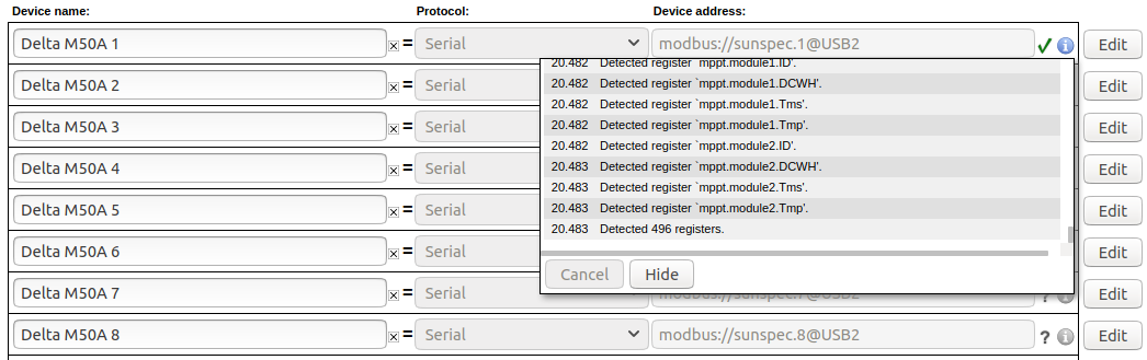
5. Click the grey "?" to the left of the device address. This will cause the eGauge to query the remote device for a full list of registers, and a green checkmark will appear if the query was successful. A red "X" will appear if the address is invalid or incorrectly entered. Click the blue info button to see detailed information on the state of the query (shown below).
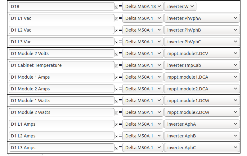
6. Once the register list has been retrieved, the eGauge needs to be configured to store registers of interest. To do this, create a new physical register, set the register type to the remote device name used in step 2, and then use the dropdown menu to select the remote register to record. The eGauge will only record the registers configured in this step, regardless of how many registers exist on the remote device.
7. Click the "Save" button at the bottom of the page to save these changes. The eGauge must be rebooted after adding new registers (this process typically takes about 30 seconds).
To add additional registers from a remote device, repeat steps 5 and 6.
Custom Modbus definitions (read from any Modbus device)
Overview
Current firmware allows the eGauge meter to record data from remote devices using Modbus RTU (using the USB485 USB-to-serial converter) and Modbus TCP (Ethernet).
If the remote device supports SunSpec over Modbus, there is not a need to create a Modbus Map. Instead, configure the remote device as a SunSpec device as described in this article.
Contents
Accessing the Modbus Map Editor
Accessing the Modbus Map Editor
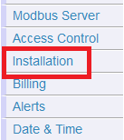
The Modbus Map Editor can be accessed through the Installation Settings screen by clicking the "Modbus Maps" button under the "Remote Devices" section:

A list of available Modbus maps will load. From here, maps can be created, edited, shared, or applied to the meter.
Creating a New Map
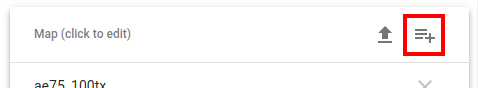
To create a new map, click or tap the icon in the top right corner of the page.
This will open a new page.
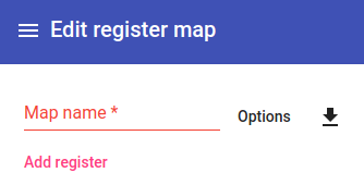
First, enter an appropriate map name. Typically, this should identify the hardware. Hardware model numbers are recommended. Click the "Save" button in the bottom right corner of the page to create an empty map with this name. The meter will load the list of available maps again, with the new (empty) map at the top. Click on this again to return to the empty map.
Adding Registers
To add registers, click the "Add Register" button. Enter the appropriate information for your register. "Scale" and "Offset" are optional values; all other fields must be filled. This information will be available in the documentation for the third party hardware - if it is not, it will be necessary to contact that hardware manufacturer directly. eGauge Systems cannot provide Modbus register maps for third party hardware.
As an example, the manufacturer's Modbus register map used to create the register below is available here: XY-MD02 manual. Note that Modbus register maps are not standardized, and it may require some effort to find the values required for eGauge configuration in a given map.
Below is an example register:
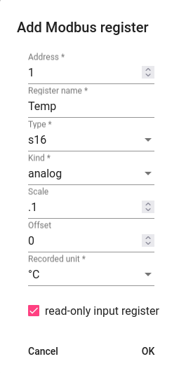
Address
Modbus register address, in decimal form. Note that Modbus documentation is not consistent, and it may be necessary to modify the address. For example, many addresses are listed with a preceding 3 or 4, but this number is usually dropped along with any preceding 0s. Thus, 30001 becomes 1, 40258 becomes 258, and so on. Some addresses may have a +/- 1 offset, so 301 might actually need to be entered as 300. Finally convert hex values (which usually start with 0x) to decimal values using a hexidecimal to decimal converter.
Register Name
The register name is an arbitrary value, but should reflect the item being measured for the sake of clarity. For example, "Temperature" implies a temperature measurement. "Ambient Temperature" might be a better fit for a device which records multiple temperature measurements.
Type
The data type of the register. If this setting is not correct the register data will not be read correctly, although it will usually read something. 32 and 64 bit data types read more than one Modbus register (a single Modbus register is 16 bits). In the absence of a defined data type, a register described by an address range (eg, 10-11, or 1000-1003) is likely a 32 or 64 bit register.
Kind
The kind of register. There are three options:
Analog - A simple numerical value. Most applications will use analog values.
Bitset - A numerical value representing a binary string. Typically, each 1 or 0 in this string would represent a state on the remote device. This selection is never averaged or allowed to accumulate excess, because it would change the fundamental value.
Enum - A numerical value representing a state on the remote device. This selection is never averaged or allowed to accumulate excess, because it would change the fundamental value.
Scale
Applies a scale factor to the raw value read from the Modbus device. This may be used to scale incoming values to better fit a certain data type. In the example above, the Temperature register at address 1 records temperature in .1 C increments, but the eGauge uses C as a unit. A raw value of 334 would therefore be displayed and recorded as 33.4 degrees Celsius with a .1 scale factor. If left blank, this is set to "1".
Offset
Applies a numerical offset to a raw value. This may be used for calibration purposes (eg, if a sensor is known to read 2 units too low, an offset of 2 would display the reading from that sensor as "raw_value + 2"). If left blank, this is set to "0".
Recorded Unit
Associates a supported unit with the value recorded from that register. This assigns a unit to the register in the eGauge user interface. For unsupported units, "record as integer" will record whole numbers and "record with 3 digits" will record fractional numbers to three digits (note that the incoming data may not actually be precise to three digits).
Read-only Input Register
The eGauge supports reading values from remote devices using either function code 3 (read holding registers) or function code 4 (read input registers). By default, function code 3 is used. However, some devices may only support function code 4 - in this case, selecting "read-only input register" will force the eGauge to use function code 4 for that register. Note that it is possible to use a mix of function codes on a single device.
Once a register has been added, click "OK" to save that register into the map. The register will be added to the map, and additional registers can be added by clicking the add icon in the top right corner of the page.
This example device has two registers, shown configured below:
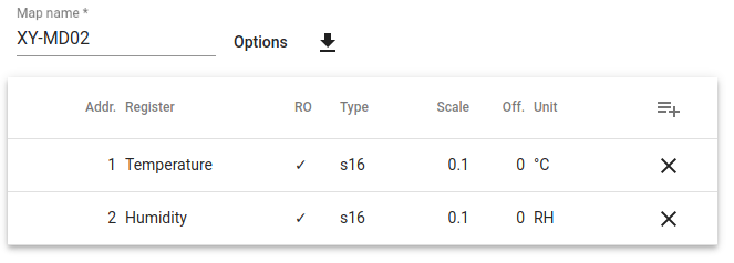
Make sure to click "Save" in the bottom right corner of the page once all registers are added. Navigating away from the page before clicking save will revert all changes (including newly added registers).
Adding Default Options
This section allows the user to specify various communication options on a per-device level. There are four options which can be set. Note that some of these options are mutually exclusive or not required depending on the device type. For example, a serial device (Modbus RTU) will not have a default TCP port.
Default Unit Number
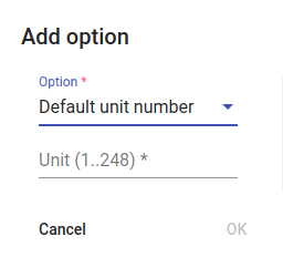
The default unit number is also referred to as "Modbus ID", "Modbus slave address", "Slave address", and so on. Each device on a single serial chain must have a unique unit number. Typically, hardware will ship with a default unit number, so if multiple devices from the same manufacturer are preset the unit number must be set to a unique value on each device.
The process for changing a device's unit number depends on the hardware - reach out to the hardware manufacturer for additional information or instructions.
Default Serial Port Parameters
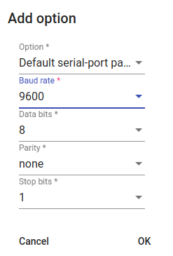
Only applies to Modbus RTU devices
Most Modbus RTU devices ship with a predefined set of serial parameters. These include baud rate, data bits, parity, and stop bits. These parameters must be identical across all devices on a single serial chain. If using multiple identical devices they should all be set to use the same values, but devices from different manufacturers may need to be set so they all use the same serial parameters.
The process for changing serial parameters depends on the hardware - reach out to the hardware manufacturer for additional information or instructions.
Default TCP Port
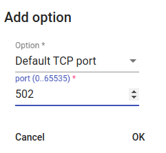
Only applies to Modbus TCP devices
Most Modbus TCP devices ship with a default TCP port of 502. However, in some cases this may not be true, or it may be desirable to use a different TCP port. TCP ports do not need to match across multiple Modbus TCP devices, even on the same network (each Modbus TCP device should have a unique IP address, so the port used is immaterial).
Base Address

The base address field can be used to apply a starting address for registers. This can be useful if a manufacturer's Modbus map has a +/-1 offset, or if the addresses all require a specific prefix (eg, 30000, 40000, 1000). The address queried by the eGauge will be (base address) + (configured address).
If in doubt, this setting can generally be ignored.
Sharing Modbus Maps
Modbus maps can be downloaded and shared as CSV files. There is no charge for this service. This can be used to copy a single map to multiple meters, or to share a map with other users. For best results, ensure that the source and destination meters are both on the same firmware version.
Always verify that maps downloaded from unknown sources are valid and complete. A misconfigured map can't cause damage to the eGauge, but it might not work correctly or may report incorrect values.
Downloading a Map
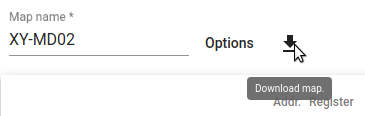
To download a Modbus map, select the desired map from the map list and click the "Download" button. A confirmation window will appear:
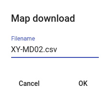
After clicking "OK", the map will be downloaded as a CSV file.
Although it is possible to edit the CSV file directly, this is not supported or recommended.
Uploading a Map
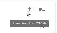
To upload a Modbus map, click the "Upload" button in the top right corner of the map list. A confirmation window will appear:
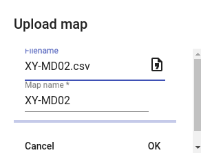
Click the "Filename" field to select the location of the saved map on your computer or device. Optionally, enter the desired map name. Click "OK" to upload the map.
An error message will appear at the bottom of the page if the map is invalid, corrupted, or incomplete.
Modbus maps can be shared freely as desired. eGauge Systems makes no guarantees as to the correctness or validity of these maps. When uploading a map, always verify that map configuration is correct and complete.
Using a Modbus Map
Once a Modbus map has been fully configured and saved, it can used in remote device addresses (under Settings -> Installation). Note that a map doesn't do anything until it's added as a remote device and at least one local register is created to store data based on that map.
The process for this varies based on whether the map applies to a Modbus RTU or Modbus TCP device. Make a note of the map name - it will be required to configure the eGauge.
Modbus RTU
Modbus RTU device addresses are prefixed with modbus:// and end with the address of either a USB port when using the USB-RS485 adapter (USB1 or USB2) or the MAC address of a Serial to Ethernet converter.
The protocol type "Serial" should be selected for all Modbus RTU devices.
In the example below, the map XY-MD02 is associated with a serial to USB adapter in USB port 1

Serial settings can also be added if default serial settings weren't specified in the map or if different serial settings need to be used. For example:

In the above example, the serial settings are:
| Baud | Data Bits | Parity | Stop Bits |
| 9600 | 8 | n (none) | 1 |
Finally, it's also possible to specify a different Modbus address/slave address/unit number. This will be necessary if a default value isn't specified or if multiple devices are on the same serial chain. To do this, add the address in the form .X after the map name, where X is the address. For example:

In the above example, an address of 55 is used instead of the default.
Modbus TCP
Modbus TCP devices have no prefix, and end with the IP address or MAC address of the Modbus device on the local network. Note that Modbus TCP devices must be on the same local network as the eGauge.
The Protocol type "Modbus TCP" should be selected for all Modbus TCP devices.
In the example below, the map XY-MD02 is associated with the address 192.168.1.25 (presumably the same network the eGauge is connected to):

A different Modbus address/slave address/unit number may also need to be specified. To do this, add the address in the form .X after the map name, where X is the address. For example:

In the above example, an address of 55 is used instead of the default.
Creating a Local Register
To create a local register and record data from a remote device, you must first validate the Modbus address. To do this, click the grey "?" to the left of the remote device address. A green check mark should appear. If a red "X" appears, it means the remote device is unreachable or the address or map is configured incorrectly.
Once the green check mark appears, registers can be added to the eGauge configuration to store data fetched from the Modbus device. In the example below, the eGauge is importing two registers ("Humidity" and "Temperature") from the remote device "Sensor":
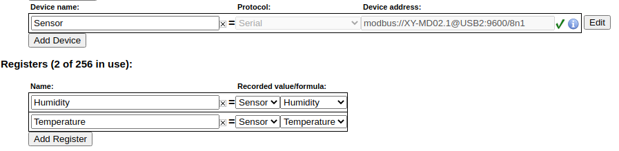
After adding registers, make sure to save changes by clicking "Save" at the bottom of the page.
For an introduction to making configuration changes to the eGauge, see this article.
Creating, Sharing, and Using Modbus Maps
Overview
Current firmware allows the eGauge meter to record data from remote devices using Modbus RTU (using the USB485 USB-to-serial converter) and Modbus TCP (Ethernet).
If the remote device supports SunSpec over Modbus, there is not a need to create a Modbus Map. Instead, configure the remote device as a SunSpec device as described in this article.
Contents
Accessing the Modbus Map Editor
Accessing the Modbus Map Editor
The Modbus Map Editor can be accessed through the Installation Settings screen by clicking the "Modbus Maps" button under the "Remote Devices" section:
A list of available Modbus maps will load. From here, maps can be created, edited, shared, or applied to the meter.
Creating a New Map
To create a new map, click or tap the icon in the top right corner of the page.
This will open a new page.
First, enter an appropriate map name. Typically, this should identify the hardware. Hardware model numbers are recommended. Click the "Save" button in the bottom right corner of the page to create an empty map with this name. The meter will load the list of available maps again, with the new (empty) map at the top. Click on this again to return to the empty map.
Adding Registers
To add registers, click the "Add Register" button. Enter the appropriate information for your register. "Scale" and "Offset" are optional values; all other fields must be filled. This information will be available in the documentation for the third party hardware - if it is not, it will be necessary to contact that hardware manufacturer directly. eGauge Systems cannot provide Modbus register maps for third party hardware.
As an example, the manufacturer's Modbus register map used to create the register below is available here: XY-MD02 manual. Note that Modbus register maps are not standardized, and it may require some effort to find the values required for eGauge configuration in a given map.
Below is an example register:
Address
Modbus register address, in decimal form. Note that Modbus documentation is not consistent, and it may be necessary to modify the address. For example, many addresses are listed with a preceding 3 or 4, but this number is usually dropped along with any preceding 0s. Thus, 30001 becomes 1, 40258 becomes 258, and so on. Some addresses may have a +/- 1 offset, so 301 might actually need to be entered as 300. Finally convert hex values (which usually start with 0x) to decimal values using a hexidecimal to decimal converter.
Register Name
The register name is an arbitrary value, but should reflect the item being measured for the sake of clarity. For example, "Temperature" implies a temperature measurement. "Ambient Temperature" might be a better fit for a device which records multiple temperature measurements.
Type
The data type of the register. If this setting is not correct the register data will not be read correctly, although it will usually read something. 32 and 64 bit data types read more than one Modbus register (a single Modbus register is 16 bits). In the absence of a defined data type, a register described by an address range (eg, 10-11, or 1000-1003) is likely a 32 or 64 bit register.
Kind
The kind of register. There are three options:
Analog - A simple numerical value. Most applications will use analog values.
Bitset - A numerical value representing a binary string. Typically, each 1 or 0 in this string would represent a state on the remote device. This selection is never averaged or allowed to accumulate excess, because it would change the fundamental value.
Enum - A numerical value representing a state on the remote device. This selection is never averaged or allowed to accumulate excess, because it would change the fundamental value.
Scale
Applies a scale factor to the raw value read from the Modbus device. This may be used to scale incoming values to better fit a certain data type. In the example above, the Temperature register at address 1 records temperature in .1 C increments, but the eGauge uses C as a unit. A raw value of 334 would therefore be displayed and recorded as 33.4 degrees Celsius with a .1 scale factor. If left blank, this is set to "1".
Offset
Applies a numerical offset to a raw value. This may be used for calibration purposes (eg, if a sensor is known to read 2 units too low, an offset of 2 would display the reading from that sensor as "raw_value + 2"). If left blank, this is set to "0".
Recorded Unit
Associates a supported unit with the value recorded from that register. This assigns a unit to the register in the eGauge user interface. For unsupported units, "record as integer" will record whole numbers and "record with 3 digits" will record fractional numbers to three digits (note that the incoming data may not actually be precise to three digits).
Read-only Input Register
The eGauge supports reading values from remote devices using either function code 3 (read holding registers) or function code 4 (read input registers). By default, function code 3 is used. However, some devices may only support function code 4 - in this case, selecting "read-only input register" will force the eGauge to use function code 4 for that register. Note that it is possible to use a mix of function codes on a single device.
Once a register has been added, click "OK" to save that register into the map. The register will be added to the map, and additional registers can be added by clicking the add icon in the top right corner of the page.
This example device has two registers, shown configured below:
Make sure to click "Save" in the bottom right corner of the page once all registers are added. Navigating away from the page before clicking save will revert all changes (including newly added registers).
Adding Default Options
This section allows the user to specify various communication options on a per-device level. There are four options which can be set. Note that some of these options are mutually exclusive or not required depending on the device type. For example, a serial device (Modbus RTU) will not have a default TCP port.
Default Unit Number
The default unit number is also referred to as "Modbus ID", "Modbus slave address", "Slave address", and so on. Each device on a single serial chain must have a unique unit number. Typically, hardware will ship with a default unit number, so if multiple devices from the same manufacturer are preset the unit number must be set to a unique value on each device.
The process for changing a device's unit number depends on the hardware - reach out to the hardware manufacturer for additional information or instructions.
Default Serial Port Parameters
Only applies to Modbus RTU devices
Most Modbus RTU devices ship with a predefined set of serial parameters. These include baud rate, data bits, parity, and stop bits. These parameters must be identical across all devices on a single serial chain. If using multiple identical devices they should all be set to use the same values, but devices from different manufacturers may need to be set so they all use the same serial parameters.
The process for changing serial parameters depends on the hardware - reach out to the hardware manufacturer for additional information or instructions.
Default TCP Port
Only applies to Modbus TCP devices
Most Modbus TCP devices ship with a default TCP port of 502. However, in some cases this may not be true, or it may be desirable to use a different TCP port. TCP ports do not need to match across multiple Modbus TCP devices, even on the same network (each Modbus TCP device should have a unique IP address, so the port used is immaterial).
Base Address
The base address field can be used to apply a starting address for registers. This can be useful if a manufacturer's Modbus map has a +/-1 offset, or if the addresses all require a specific prefix (eg, 30000, 40000, 1000). The address queried by the eGauge will be (base address) + (configured address).
If in doubt, this setting can generally be ignored.
Sharing Modbus Maps
Modbus maps can be downloaded and shared as CSV files. There is no charge for this service. This can be used to copy a single map to multiple meters, or to share a map with other users. For best results, ensure that the source and destination meters are both on the same firmware version.
Always verify that maps downloaded from unknown sources are valid and complete. A misconfigured map can't cause damage to the eGauge, but it might not work correctly or may report incorrect values.
Downloading a Map
To download a Modbus map, select the desired map from the map list and click the "Download" button. A confirmation window will appear:
After clicking "OK", the map will be downloaded as a CSV file.
Although it is possible to edit the CSV file directly, this is not supported or recommended.
Uploading a Map
To upload a Modbus map, click the "Upload" button in the top right corner of the map list. A confirmation window will appear:
Click the "Filename" field to select the location of the saved map on your computer or device. Optionally, enter the desired map name. Click "OK" to upload the map.
An error message will appear at the bottom of the page if the map is invalid, corrupted, or incomplete.
Modbus maps can be shared freely as desired. eGauge Systems makes no guarantees as to the correctness or validity of these maps. When uploading a map, always verify that map configuration is correct and complete.
Using a Modbus Map
Once a Modbus map has been fully configured and saved, it can used in remote device addresses (under Settings -> Installation). Note that a map doesn't do anything until it's added as a remote device and at least one local register is created to store data based on that map.
The process for this varies based on whether the map applies to a Modbus RTU or Modbus TCP device. Make a note of the map name - it will be required to configure the eGauge.
Modbus RTU
Modbus RTU device addresses are prefixed with modbus:// and end with the address of either a USB port when using the USB-RS485 adapter (USB1 or USB2) or the MAC address of a Serial to Ethernet converter.
The protocol type "Serial" should be selected for all Modbus RTU devices.
In the example below, the map XY-MD02 is associated with a serial to USB adapter in USB port 1
Serial settings can also be added if default serial settings weren't specified in the map or if different serial settings need to be used. For example:
In the above example, the serial settings are:
| Baud | Data Bits | Parity | Stop Bits |
| 9600 | 8 | n (none) | 1 |
Finally, it's also possible to specify a different Modbus address/slave address/unit number. This will be necessary if a default value isn't specified or if multiple devices are on the same serial chain. To do this, add the address in the form .X after the map name, where X is the address. For example:
In the above example, an address of 55 is used instead of the default.
Modbus TCP
Modbus TCP devices have no prefix, and end with the IP address or MAC address of the Modbus device on the local network. Note that Modbus TCP devices must be on the same local network as the eGauge.
The Protocol type "Modbus TCP" should be selected for all Modbus TCP devices.
In the example below, the map XY-MD02 is associated with the address 192.168.1.25 (presumably the same network the eGauge is connected to):
A different Modbus address/slave address/unit number may also need to be specified. To do this, add the address in the form .X after the map name, where X is the address. For example:
In the above example, an address of 55 is used instead of the default.
Creating a Local Register
To create a local register and record data from a remote device, you must first validate the Modbus address. To do this, click the grey "?" to the left of the remote device address. A green check mark should appear. If a red "X" appears, it means the remote device is unreachable or the address or map is configured incorrectly.
Once the green check mark appears, registers can be added to the eGauge configuration to store data fetched from the Modbus device. In the example below, the eGauge is importing two registers ("Humidity" and "Temperature") from the remote device "Sensor":
After adding registers, make sure to save changes by clicking "Save" at the bottom of the page.
For an introduction to making configuration changes to the eGauge, see this article.
BACnet
eGauge meters can output BACnet information via MS/TP and IP (UDP)
BACnet Overview
Quick Links:
• BACnet register map and PICS
• Configuring BACnet service
What is BACnet?
BACnet is a communication protocol designed for Building Automation and Control (Networks), for use with a Building Automation System (BAS) which controls and automates certain functions within a building. A BAS typically receives data from multiple remote devices, such as temperature, electrical consumption, air quality, and many other types of data depending on what is or can be automated in the building. Based on this data, the BAS can send alerts to building managers and control loads, such as turning on heating if an area becomes too cold or turning off non-critical systems to load shed when overall consumption becomes too high.
eGauge compatibility
The eGauge can provide BACnet data over an Ethernet LAN (BACnet IP) as well as over RS485 serial (BACnet MS/TP). Any data the eGauge collects, including from other remote devices, are available to send
General overview
A building automation system (BAS) will periodically request data from a remote device (e.g., the eGauge meter), and based on this data it may do nothing, trigger an alarm, or switch on or off loads or other controllable equipment.
BACnet is disabled by default on the eGauge meter and may be enabled through Settings → BACnet. For an example of the configuration and options available see this knowledgebase article.
BACnet MS/TP (Serial)
Using the eGauge USB485, the eGauge meter can provide data via BACnet to a building automation system.
Be sure to review general (non-eGauge specific) serial communication considerations when considering serial lines for BACnet communication. This includes but not limited to:3CmxGraphModel%3E%3Croot%3E%3CmxCell%20id%3D%220%22%2F%3E%3CmxCell%20id%3D%221%22%20parent%3D%220%22%2F%3E%3CmxCell%20id%3D%222%22%20value%3D%22%26lt%3Bfont%20color%3D%26quot%3B%23ff3333%26quot%3B%26gt%3BData%20from%20eGauge%20Meter%20electrical%20readings%20are%20sent%20to%20Building%20Automation%20System%26lt%3B%2Ffont%26gt%3B%22%20style%3D%22text%3Bhtml%3D1%3BstrokeColor%3Dnone%3BfillColor%3Dnone%3Balign%3Dcenter%3BverticalAlign%3Dmiddle%3BwhiteSpace%3Dwrap%3Brounded%3D0%3BfontSize%3D15%3B%22%20vertex%3D%221%22%20parent%3D%221%22%3E%3CmxGeometry%20x%3D%22530.23%22%20y%3D%22580%22%20width%3D%22150%22%20height%3D%2280%22%20as%3D%22geometry%22%2F%3E%3C%2FmxCell%3E%3C%2Froot%3E%3C%2FmxGraphModel%3Eaaaaaadasdas
• Using twisted pair wire for data +/- lines
• Choosing appropriate wire gauge and baud rate (becomes increasingly important with long wire runs)
• Appropriate termination methods (the eGauge USB485 has a selectable termination switch)
• Software and hardware configuration for BAS system controller
BACnet IP (over an Ethernet network)
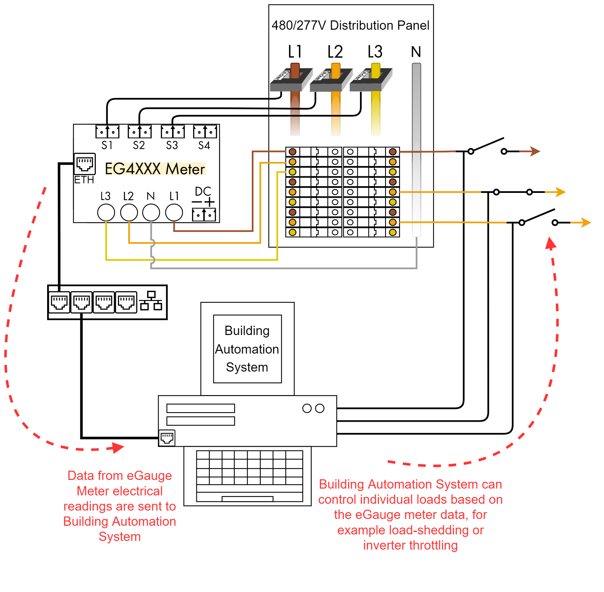
BACnet over a LAN has the same functionality as BACnet MS/TP over serial, but it uses an Ethernet network and can connect to an existing LAN instead of requiring its own serial chain.
BACnet register map and PICS
The eGauge does not have a fixed BACnet register map. Instead, registers are mapped as they are created. Thus, the map for two different eGauges will differ based on the number of registers and the order they were added in. Registers are organized into groups, which are defined below.
The BACnet PICS (Protocol Implementation Conformance Statement) may be found here. The article you are viewing has more "human-friendly" information for the BACnet data meters provide.
If a static IP address is used with an incorrect broadcast address, BACnet communication may not function properly and the meter may not be discoverable.
Group 5 and Group 6 addresses may change if register configuration is modified. It is recommended to use range 0xb0000 and 0xc0000 as the addresses numbers are tied to the register ID and will always remain in that order. See this article for more information about register IDs. Beginning in firmware v4.6 deprecated ranges will be identified as 'old'.
| Address Range | Group Description | Measured Value | See footnote |
| 0x20000 | Group 1 - The RMS voltage of the voltage-taps can be read through this group. | Voltage [V] |
|
| 0x30000 | Group 2 - The RMS current measured by each sensor/CT can be read through this group. | Current [A] | 1 |
| 0x50000 | Group 3 - The frequency of the voltage-taps can be read through this group. | Line Frequency [Hz] | |
| 0x60000 |
Group 4 contains only the object ID 0x60000 and it reports the number of seconds since BACnet daemon startup. The daemon starts after enabling BACnet support through the UI or after power-cycling. |
Timestamp [s] | |
| 0x70000 |
Group 5 reports the register value for each register (virtual and physical). The register values are time-weighted values and hence the unit of these object IDs is equal to the unit of the corresponding object ID in Group 6, multiplied by seconds. For example, for a register recording power, the Group 6 unit would be Watts, and therefore the Group 5 unit would be Watt-seconds (i.e., Joules). DEPRECATED IN v4.0, use range 0xb0000 to 0xbffff in firmware v4.0 and newer. CHANGED IN v4.6, from REGVAL to OLDVAL |
OLDVAL [various] | |
| 0x80000 |
Group 6 reports, for each virtual and physical register, the change in register value during the most recent one-second interval. For example, for a register recording power, the unit would be Watts, for a register recording voltage, the unit would be Volts. DEPRECATED IN v4.0, use range 0xc0000 to 0xcffff in firmware v4.0 and newer. CHANGED IN v4.6, from REGCHG to OLDCHG |
OLDCHG [various] | |
| 0x90000 | Mean Voltages - mean (DC) voltages for voltage inputs | Voltage [V] | 2 |
| 0xa0000 | Mean Sensor Values - mean (DC) values for sensor/CT inputs | Current [A] | 1, 2 |
| 0xb0000 | Register values like Group 5, statically indexed by register ID | REGVAL [various] | 2, 3 |
| 0xc0000 | Register rate-of-change (instantaneous) values like Group 6, statically indexed by register ID | REGCHG [various] | 2, 3 |
Footnotes:
1. Unit will be Amps for current, various for other sensors
2. Introduced in firmware v4.0
3. These addresses are tied to register ID. Group 5 and Group 6 are liable to have addresses change if register configuration is modified.
Additional Tips:
- Cumulative register values are found in Group 0xb, REGVAL. This provides time-weighted values such as kWh or amp-hours.
- Cumulative register values may not start at zero. Thus, it is important to compare a previously received value with the current value to determine the total value change between two points in time.
- Instantaneous (rate-of-change) register values are found in Group 0xc, REGCHG. These provide instantaneous values such as Watts or Amps.
- The physical unit of this register depends on the quantity being recorded and can be obtained by reading the "unit" property (BACnet property 117) of the respective object id.
- The register name for a given object ID can be obtained by reading the "name" property (BACnet property 77) from the object ID.
- In Group 0x70000 and 0x80000, the first two object IDs will always be the Usage and Generation virtual registers. Any additional virtual registers come next. Physical registers are listed last.
- The BACnet service is enabled on the eGauge through Settings → BACnet.
Configuring BACnet service
If a static IP address is used with an incorrect broadcast address, BACnet communication may not function properly and the meter may not be discoverable.
The eGauge meter can provide data via BACnet IP and BACnet MS/TP (only available on EG4xxx meters). The BACnet service is disabled by default and may be enabled through Settings → BACnet.
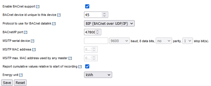
| Option | Description |
| Enable BACnet support | Enables the BACnet service on the meter. Disabled by default. |
| BACnet device id unique to this device | Each BACnet capable device needs to have a unique device instance number, which can be any number between 0 and 4,194,303. |
| Protocol to use for BACnet datalink |
|
| BACnet/IP port | The BACnet IP port is defined as UDP 47808, but may be changed if required here (only applies to BACnet IP). |
| MS/TP serial device | If BACnet MS/TP is chosen, click inside the input box to display any USB485 converters connected to the eGauge USB ports. Baud, Parity and Stop Bits may also be configured (these must match the BACnet controller that requests data from the meter). |
| MS/TP MAC address | The MS/TP MAC address used by eGauge. Every BACnet device on an MS/TP bus requires a unique MAC address. eGauge acts as a master so its address is limited from 0 to 127. For best performance, MS/TP MAC addresses should be assigned consecutively starting at zero. For example, if there are three MS/TP devices, MAC addresses 0, 1, and 2 would yield the best performance. |
| MS/TP max. MAC address used by any master | This should be set to the maximum MS/TP MAC address that is in use. 127 is a safe value, but for best performance, it is recommended to set this to the lowest possible value instead. For example, if there are three MS/TP devices with MAC addresses 0, 1, and 2, this value should be set to 2 on all three devices. |
| Report cumulative values relative to start of recording | This should generally be enabled and is for backwards-compatibility. Enabling ensures the meters first meter reading is 0, otherwise it may be an arbitrary value. |
| Energy unit | May be set in either watt-seconds (Joules) or kWh |
Serial and USB485
General USB485 and serial information
Remote device via eGauge USB485 adapter
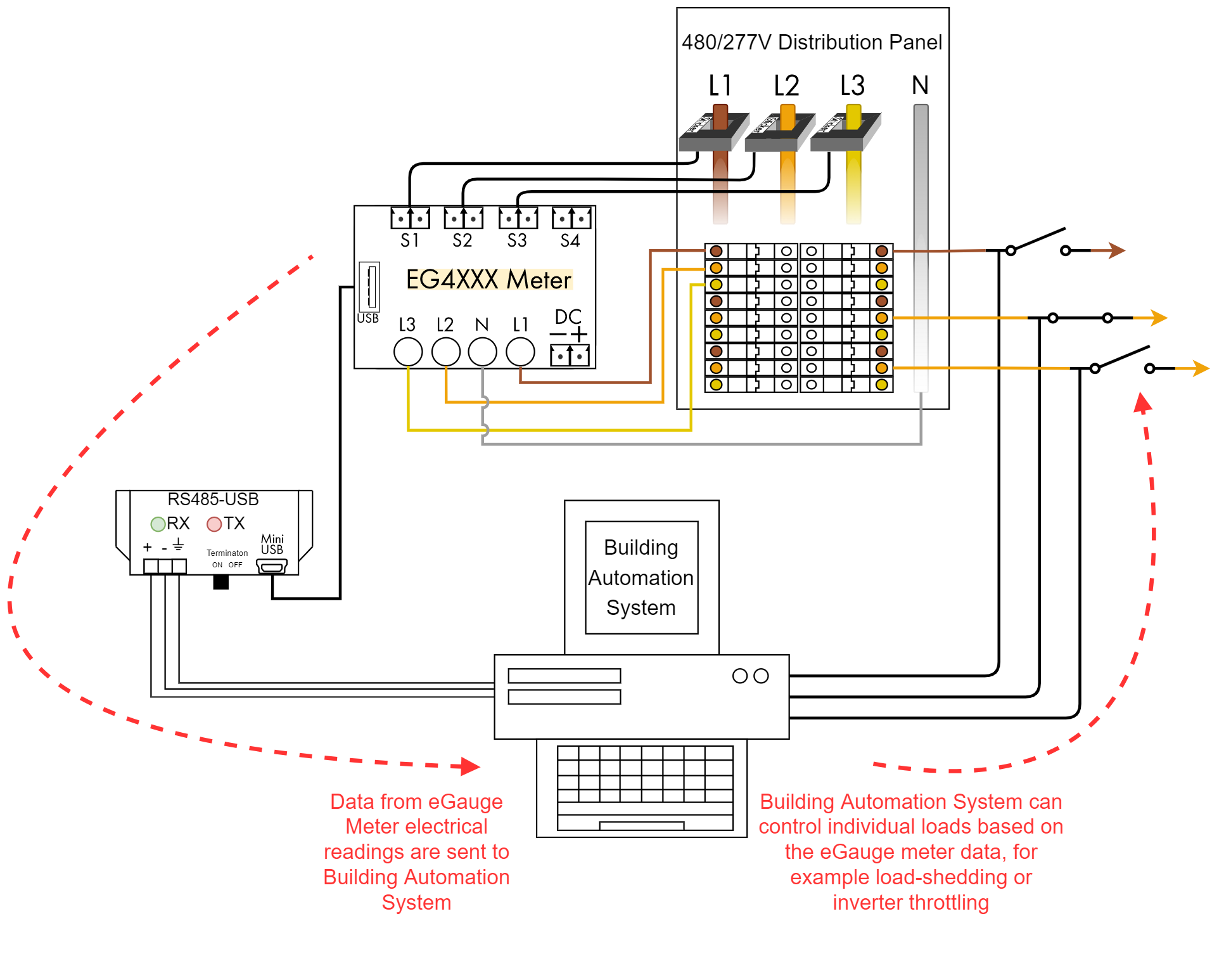
The EG4xxx has two USB ports which may be utilized for communicating with third-party serial devices via the eGauge RS485-USB converter (USB485). This effectively replaces the BF-430 used with older model eGauges. In addition, a network connection is not required, as data is read from the third-party serial device through the RS485-USB converter (which is physically connected to the eGauge). At the end of this document is a wiring diagram illustrating the required connections between an eGauge and a single third-party serial device using the RS485-USB converter. Specific wiring diagrams for the commonly used IMT SI-RS485TC irradiance sensor are also available.
The RS485-USB Converter features include:
- Micro-USB interface
- 3-wire RS485 terminal interface (data+, data-, ground)
- Termination switch
- 2 LEDs, to indicate TX and RX activity
|
The USB ground is tied to the eGauge DC voltage ground terminal. If the DC voltage terminal is wired in reverse, a significant ground potential may form and damage will occur! |

Topics in this article include:
- RS485 Interface Grounding
- Termination
- eGauge configuration
- Configuring additional serial parameters
- Indicator LEDs
- Standard wiring diagram
RS485 interface grounding
A ground between the RS485-USB converter and serial device's power supply may be required. If the ground potential between the sender and receiver are too far off, the communication voltage can run outside of acceptable limits resulting in communication degradation or even damage to connected equipment.
It is recommended to connect the ground connection before the data cables.
If the serial device is powered via one of the eGauge USB ports, the ground connection is not needed.
Termination
The RS485-USB Converter has a termination toggle switch. This should be enabled if the converter is the last device on the chain, or if there is only a single serial device connected. In most cases this termination switch should be in the ON position. Failure to enable the termination switch may result in communication degradation or failure.
eGauge Configuration
The configuration for an eGauge to communicate with a remote serial device using the RS485-USB Converter is similar to configuring other remote devices. Navigate to Settings -> Installation and add a new remote device using protocol "Serial". The device address is either USB1 or USB2, depending on the USB input in use. All other remote device configuration is standard, and more information on the device address syntax for custom Modbus definitions can be found in the third party device section of eGauge.net.
|
Example remote device address for a Modbus IMT irradiance sensor with serial address 1 via RS485-USB converter in USB port 1 |

Configuring additional serial parameters (i.e., baud rate, data bits, parity, stop bits)
If the default serial parameters for a supported device change, or if an unsupported Modbus device with in-line definitions is used, serial parameters may need to be defined in the device address. To specify serial parameters, append to the end of the remote device address (do not include brackets):
:[BAUD_RATE]/[DATA_BITS][PARITY][STOP_BITS]
For example, modbus://imt_si.1@USB1:19200/8e2 will look for a Modbus IMT sensor with serial address 1 on USB port 1, with 19200 baud, 8 data bits, even parity, and 2 stop bits.
Similarly, modbus://temperature=2,s32,degC.3@USB2:1200/8n1 will read a signed 32-bit (s32) temperature value from register 2 from a Modbus device at serial address 3, connected via an RS485-USB converter in USB port 2, running at 1200 baud, 8 data bits, no parity, and one stop bit.
Parity options are 'e' for even, 'n' for none, and 'o' for odd.
Indicator LEDs
The eGauge RS485-USB Converter has 2 indicator LEDs. The left-side green LED flashes to indicate serial data was received (responses from the remote serial device), while the right-side red LED flashes to indicate data was received from the eGauge (requests from the eGauge to the serial device).
If there is only activity on the red LED, and no green LED flashes, it is an indication that the serial device is not responding or is not receiving the requests from the eGauge. This may be due to incorrect wiring or incorrect configuration of the eGauge remote device address, or of the serial device itself.
Standard wiring diagram
Below is the standard wiring diagram for an eGauge communicating to a single serial device via the RS485-USB Converter. An external power supply for the serial device is generally needed, but if the serial device can be powered via USB, an unused USB port on the eGauge may be connected for the power, and voltage and ground wires in the diagram ignored. It is recommended to connect the ground connection before the data cables, unless the serial device is powered from one of the USB ports on the eGauge.

Using the USB485 converter with Windows 10
The eGauge USB485 converter may be used as a standard serial-to-USB converter on a computer to read data from an eGauge or communicate with other third party devices besides the eGauge. The eGauge USB485 uses the FT230X chipset from FTDI. Up to date systems should already have the FTDI drivers available for use. If the FTDI drivers are not installed, drivers and information are available from the FTDI website at http://www.ftdichip.com/FTDrivers.htm. COM port downloads can be found at https://www.ftdichip.com/Drivers/VCP.htm.
This article describes how to verify the USB485 converter is recognized by a Windows 10 machine, and uses QModBus to show data being read from an eGauge via two USB485 converters.
Note that support for third party devices is not guaranteed.
1) Connect the eGauge USB485 via USB to the Windows 10 machine. After a minute or several, a notification indicating the serial converter drivers are ready will be displayed at the bottom right-hand corner. If this does not appear after 5 minutes, verify the USB cable is secure and move to the next step.

2) Open the device manager by pressing the Windows Key and R (Win+R) to open the "Run" prompt. Alternatively open the start menu, and type "run" and press enter to open the run prompt. Enter devmgmt.msc in the text box and press "OK":

3) Under "Universal Serial Bus controllers" you should see "USB Serial Converter":

4) You can determine the COM port by expanding "Ports (COM & LPT)". Here, it is COM3:

5) The QModBus program may be installed from http://qmodbus.sourceforge.net. eGauge Systems does not endorse and cannot validate the legitimacy of the QModBus program. When the QModBus program is installed and executed, if no serial converters are found it will warn you:

6) If a serial converter is detected, the QModBus will default to use one that is found (in our case, COM3). Here, we have configured the serial settings to match with an eGauge Modbus slave connected via serial to this Windows computers USB485 converter. In the screenshot below, we read registers 1012 and 1013, as DC voltage is a 32-bit float starting at address 1012. When converting 0x4143 and 0xB07B as a big endian float, we see the DC voltage is about 12.23.

Displaying the Manage Router option on Samsung mobile devices
When connecting to an EG42xx meter with some Samsung mobile devices the 'Manage router' option is not immediately visible in the WiFi network settings. This has to do with how the Samsung software handles captive portal login.
To force it to show, try these steps:
- Connect to the AP as usual.
- Tap the gear icon for the connected AP network, then tap the 'Forget' icon at the bottom of the screen
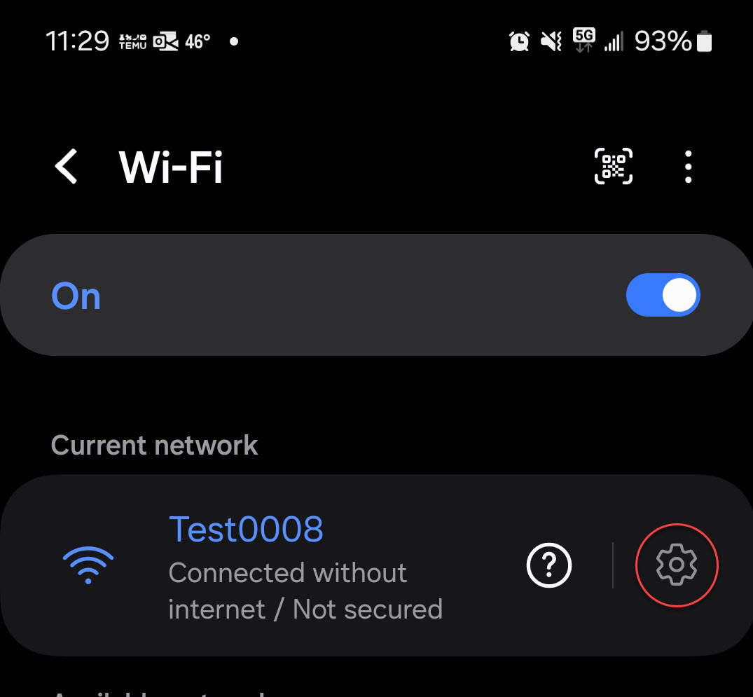
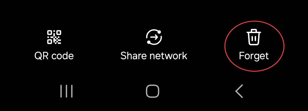
- Reconnect to the AP and choose 'Always connect' when the 'Internet may not be available' screen comes up.
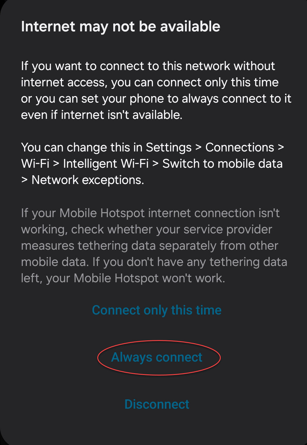
- Click the Gear icon again and the 'manage router' option should be there. Tap it to launch the eGauge interface.
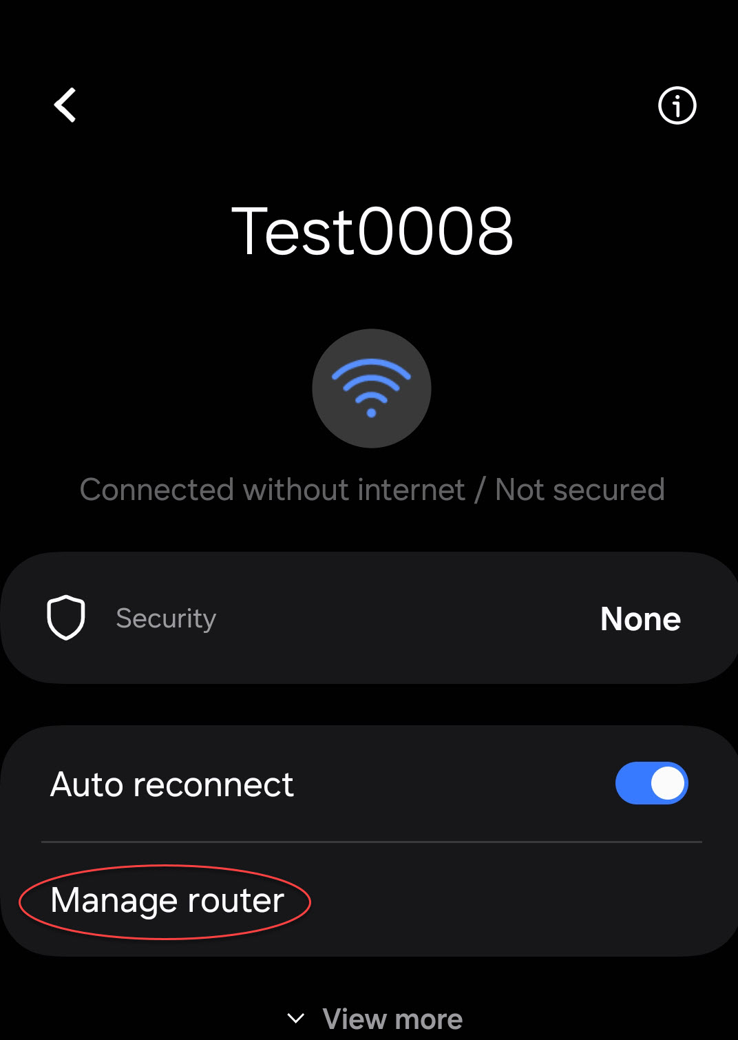
HomePlug power-line communication
All about HomePlug power-line communication
What do the different LEDs on the HomePlug adapter mean?
EG4xxx and EG30xx meters can function with a wide variety of HomePlug AV compliant powerline communication adapters. Some officially supported adapters and their LED keys are shown below.
TRENDnet HomePlug AV (TPL-406E2K) |
|||
| LED |
Function |
Typical Behavior |
Other Behavior |
| POWER | Indicates the adapter has power | Green light | No LED - no communication for too long or not receiving power |
| ETHERNET | Indicates an Ethernet line connection | On - live Ethernet line connected Blinking - sending/receiving Ethernet data |
Off - may indicate an issue with network connectivity or a damaged Ethernet cable |
| DATA | Indicates presence of powerline communication | On - Powerline device connected Blinking - sending/receiving powerline data |
Off - no connection to any HomePlug devices |

TP-Link HomePlug AV (TL-PA2010)
|
|||
| LED |
Function |
Typical Behavior |
Other Behavior |
 |
Indicates the adapter has power | Green light | No LED - no Ethernet communication for too long or not receiving power |
 |
Indicates a connection with the eGauge or another HomePlug AV adapter | Blinking green when communicating with the eGauge | Off - no connection to any HomePlug AV devices |
 |
Indicates an Ethernet line connection | Blinking green light when transmitting data | Off - may indicate an issue with network connectivity or a damaged Ethernet cable |
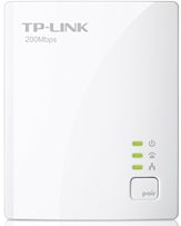
Actiontec HomePlug AV (PWR500/PWR200) |
|||
| LED | Function | Typical Behavior | Other Behavior |
| PWR | Indicates the adapter has power | Green light | No LED - no Ethernet communication for too long or not receiving power |
| LK | Indicates a connection with the eGauge or another HomePlug AV adapter | Blinking red light when communicating with the eGauge | Blinking orange or green - possible connection with another HomePlug AV device Off - no connection to any HomePlug AV devices |
| ETH | Indicates an Ethernet line connection | Blinking green light when transmitting data | Off - may indicate an issue with network connectivity or a damaged Ethernet cable |
HomePlug 1.0 HPE100T |
|||
| LED | Function | Typical Behavior | |
| Power | Adapter has power and is connected to the eGauge or another HomePlug 1.0 device | Green light when active, blinking green light when transmitting data | Off - adapter is not receiving power, or cannot communicate to the eGauge |
| Link | Indicates an Ethernet line connection | Green when active, blinking green when transmitting data | Off - issue with network connectivity or a damaged Ethernet cable |
NOTE: Other HomePlug adapters from different manufacturers may work. However, since they have not been tested by eGauge we cannot guarantee full functionality. Troubleshooting and support may be limited in these situations. HomePlug 1.0 adapters are no longer available directly through eGauge - please see our article on locating replacement HomePlug 1.0 adapters for more information.
Can the HomePlug adapter be connected to a power strip?
HomePlug adapters should be connected directly into a wall outlet. If that is not an option, it is possible to plug the HomePlug into a power strip provided the power strip has no integrated surge suppressor. Most power strips designed for computers have integrated surge suppressors, so they are not suitable. Uninterruptible power supplies or power strips connected to uninterruptible power supplies are also not suitable.
Low-cost power strips are available at local hardware stores and generally work fine. Non-surge suppressed power strips may be referred to as "relocatable power taps". "Multi outlet taps" are also generally suitable. Extension cords may be used, but keep in mind that the length of the extension cord must be factored into the distance between the eGauge and HomePlug (40ft of wire run + 25ft of extension cord = 65ft between the eGauge and HomePlug). Maximum effective communication distance is approximately 100ft.
HomePlug Security Considerations
Overview

Some eGauge models have integrated powerline communication, commonly known as "HomePlug communication" or just "HomePlug". These eGauge models inject a signal into the conductor connected to the L1 terminal of the eGauge and attempt to communicate with other powerline communication devices that are within range connected to the same power line using the HomePlug standard. This effectively acts as a powerline-Ethernet bridge when used to connect an eGauge to a network with a HomePlug adapter.
eGauge2 model units utilize the "HomePlug 1.0" protocol, while newer model eGauges (EG31xx, EG41xx) utilize the newer "HomePlug AV" protocol. "HomePlug AV" is not backwards compatible with "HomePlug 1.0", and the devices will not see each other or communicate. The HomePlug 1.0 standard is no longer in common use, and HomePlug 1.0 adapters may not be readily available.
The HomePlug signal’s reach is limited to about 100ft of wiring and does not extend beyond transformers or cross phases. Thus, for most single-family homes, the HomePlug signal will be contained to within the home itself. This is in contrast to a WiFi signal, for example, which usually can be picked up easily outside a home.
Security Considerations
All HomePlug devices have a "password" or "encryption key" assigned to them. Any HomePlug devices with the same encryption key can communicate to each-other and form a "HomePlug network". By default, the HomePlug 1.0 encryption key is "HomePlug" (case sensitive, without quotes) while the HomePlug AV default encryption key is "HomePlugAV" (case sensitive, without quotes).
Because the HomePlug devices come with default encryption keys, buildings that share electrical services (e.g., possibly duplexes, apartment buildings) may have the HomePlug signal extended into neighboring units which could then allow an individual to obtain someone else's network access via a HomePlug adapter if both are using the default encryption keys. Therefore, it is important to set a unique encryption key on any HomePlug networks that may share a power line with another unit.
HomePlug AV (models EG31xx, EG41xx) utilize the HomePlug Green PHY specification and are compatible with HomePlug AV using 128-bit AES encryption.
HomePlug 1.0 (model eGauge2) utilize a HomePlug 1.0-compatible link and are encrypted with 56-bit Data Encryption Standard (DES).
It is best practice to utilize a unique and secure HomePlug encryption password, but in many private residences it is unlikely to be an issue because of the limitations of powerline communication (specifically, it is unlikely the HomePlug signal will propagate beyond the building's electrical wiring).
More information can be found on the HomePlug Alliance website at http://www.homeplug.org/.
Related Articles
Pairing an eGauge with a HomePlug adapter
What do the different LEDs on the HomePlug adapter mean?
What are some common causes of HomePlug communication issues?
How do I pair the eGauge with a HomePlug adapter?
Overview
By default all HomePlug-compliant PLC devices use the same encryption key - this means that, out of the box, any HomePlug-compliant device should be able to connect to any other HomePlug-compliant device without any adjustments. However, if there are multiple HomePlug adapters in the same location, or if there are security concerns regarding PLC traffic, it may be necessary to pair an eGauge with its HomePlug adapter. This is typically not required for most installations.
This article has instructions for pairing eGauge devices with their respective HomePlug adapters. Also included are instructions to rescue an "orphaned" device (that is, an eGauge or HomePlug with an unknown encryption key). These steps typically cannot be performed remotely, and require physical access to both the eGauge meter and the HomePlug.
In new installations, pairing is optional but not required. The eGauge and HomePlug adapter should communicate out of the box. If they do not communicate, there is likely a distance or installation issue; pairing will not correct these issues.
The internal HomePlug MAC address may be different than the MAC address printed on the meter label. For pairing EG4xxx meters, use a MAC address one higher than the one printed on the label. The MAC address on the label is what the LAN will see; the "internal" address that is one higher is used on the powerline network.
Contents
What is HomePlug and how is it used?
Technical And Environmental Considerations
How Secure is HomePlug Communication?
Changing the HomePlug Encryption Key (pairing)
HomePlug Adapter Push Button Timing
Pairing through the eGauge user interface
HomePlug Basics
What is HomePlug and how is it used?
HomePlug is a Power Line Communications (PLC) specification used to transmit networking data over standard power lines. Thus, all HomePlug devices are PLC devices, but not all PLC devices use HomePlug. It is commonly used to create a network bridge in a location where Wi-Fi can not work or is not convenient. Think of the HomePlug adapter as a "translator" that can convert an Ethernet signal into a form which can be sent over existing power lines, and vice versa. HomePlug adapters may commonly be referred to as "HomePlugs", although this can be confusing.
HomePlug adapters are commonly mistaken for wireless (WiFi) devices. Standard HomePlug adapters have no wireless component. A physical connection to an outlet and a router (via Ethernet) is required.
Typically, one HomePlug adapter is connected to a router with Internet access, and another is placed elsewhere in the building so Ethernet-capable network devices may connect to it. eGauge meters have a built-in HomePlug adapter, so only one HomePlug adapter is required when using an eGauge. Examples of common HomePlug adapters are shown below:
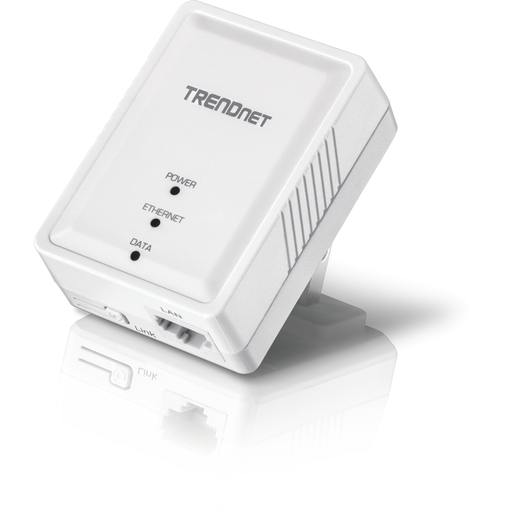
TRENDNet TPL-406E
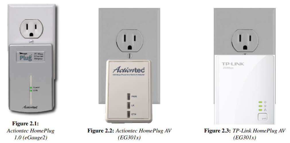
Older (legacy) HomePlug adapters. No longer available through eGauge but may be used at older sites.
Technical And Environmental Considerations
Phasing - HomePlug communication travels along the phase connected to L1 of the eGauge. The HomePlug adapter must be plugged into an outlet on the same phase as L1. Connecting the HomePlug to the wrong phase can cause issues with communication speed and quality.
Signal Deterioration and Loss - HomePlug signals can be filtered out by surge suppressors and noise filters, and will deteriorate as the length of wire between the eGauge unit and HomePlug outlet increases. This article covers several potential causes for HomePlug communication issues.
Voltage Limitations - The HomePlug AV adapters sold by eGauge Systems LLC are rated for voltages up to 240Vac (50 or 60Hz).
Although it is not recommended, eGauge Systems LLC stocks a powered enclosure kit for 277V/480V services which will step down 277Vac down to 120Vac. The transformer is rated at 25VA , suitable for powering several small devices with a combined load < 25VA. Please see this page for more information.
Multiple HomePlugs on a Network - A single HomePlug adapter can support up to 16 HomePlug devices (eGauge meters) under ideal conditions. Communication may be affected above that limit.
Issues can arise if there are multiple HomePlug adapters connected to the same network. For example, if two eGauge meters and two HomePlugs are connected to the same network, a network loop may occur. The solution is to pair each meter with a specific HomePlug adapter.
How Secure is HomePlug Communication?
EG4xxx and EG301x models use the HomePlug Green PHY specification and are compatible with devices using the HomePlug AV standard. This standard uses 128-bit AES encryption.
eGauge2 models use the HomePlug 1.0 specification and are compatible with devices using the HomePlug 1.0 standard. This standard uses 56-bit DES encryption.
HomePlug 1.0 compliant adapters are considered obsolete, and are no longer sold directly by eGauge Systems. Replacing eGauge2 meters is recommended. This article has more information.
The range of a HomePlug signal is usually restricted to a single building. More specifically, most utility transformers will completely filter the HomePlug signal. For this reason, there is little risk of a third party intercepting HomePlug communication. Furthermore, due to the nature of the HomePlug standard, even if the HomePlug signal were detectable it would be exceptionally difficult for a third-party device to interpret the point-to-point traffic between two HomePlug devices. Therefore, for most owners of HomePlug devices, privacy of communication is assured without any further steps.
Even if a neighbor could pick up the HomePlug signal, any traffic other than broadcast traffic is difficult to snoop on because the transmission-characteristics of power-lines is so poor that, in practice, communication between any pair of devices cannot be picked up by a third device. In other words, the worst that could happen in such a scenario is that the neighbor could pick up some broadcast traffic or could use your Internet connection for their own purposes.
For extra security and when using HomePlug devices in an apartment or condo or where multiple residences may be powered by a single transformer, it is possible to set a new encryption key to "pair" HomePlug devices. The default key can be changed under Settings -> HomePlug (all models) or by using push-button pairing (some models).
HomePlug 1.0 devices use the default key HomePlug
HomePlug AV devices use the default key HomePlugAV
Changing the HomePlug Encryption Key (pairing)
All HomePlug AV devices (including the eGauge meter) ship with the same default encryption key, meaning all HomePlug AV devices can pair with one another out of the box. However, it may be desirable to pair a specific eGauge and HomePlug adapter (eg, to prevent network loops or increase security). Once paired, the eGauge and HomePlug will only see one another, and will not be able to communicate with other HomePlug AV devices. The method to enter pairing depends on the meter model.
Push Button Method (EG301x meters)
EG301x meters feature push button pairing. With this option, the eGauge and a HomePlug can be paired without network access to the meter.
Physical access to the eGauge meter is required. Depending on the installation, there may be a risk of electric shock.
EG301x meters have a small push button located to the right of the Ethernet port. The push button is recessed behind a small hole. Use a 0.8mm paper clip or similar instrument to access the push button. This push button can be used to initiate join mode, leave mode, or factory reset the meter. The function depends on how long the push button is held down. The timing windows for each function are listed below.
Note that the status LED is used to indicate which function is currently selected; releasing the push button activates that function.
EG301x Push Button Timing
| Push Duration | Status LED | Description |
| 0.5 - 3 seconds | rapidly blinks blue/off | Join Mode: eGauge will attempt to pair with an existing HomePlug AV network |
| 13 - 16 seconds | rapidly blinks red/blue | Leave Mode: eGauge will randomize its HomePlug AV key, effectively unpairing the meter |
| 20 - 30 seconds | rapidly blinks red/green | Factory Reset: eGauge restores itself to factory settings |
Continuing to hold the push button for longer than 30 seconds will skip all functions without making any changes. Note that the timing window for these functions are very tight. It's crucial to release the push button as soon as the desired color code presents itself.
A factory reset will reset all settings on the meter and result in the loss of any recorded data.
LCD Method (EG41xx meters)
EG41xx meters feature an external LCD and multi-position switch. With this option, the eGauge and a HomePlug can be paired without network access to the meter. No special tools are required.
Physical access to the eGauge meter is required. Depending on the installation, there may be a risk of electric shock.
Using the multi-position switch, navigate to the HomePlug menu. Starting from the default "list of registers" view:
Toggle left or right until "Settings" is highlighted. Press the button in once.
Toggle left or right until "HomePlug" is highlighted. Press the button in once.
There are three options of interest under the "HomePlug" menu. Press the button in once to select the appropriate option.
EG41xx HomePlug Menu Options
| Option Name | Function |
| Join Others | Join Mode: eGauge will attempt to pair with an existing HomePlug AV network |
| Random PW | Leave Mode: eGauge will randomize its HomePlug AV key, effectively unpairing the meter |
| Default PW | Sets the HomePlug AV key back to the default: HomePlugAV |
The full manual on the EG4xxx LCD can be found here.
HomePlug Adapter Push Button Timing
Most HomePlug AV adapters will have a push button which can also be used to enter join mode or leave mode. Note that the timing windows vary across models and manufacturers. The timing windows below are for adapters commonly sold by eGauge Systems; it may be necessary to consult the manufacturer's documentation for other models.
TRENDNet TPL-406E HomePlug AV
| Push Duration | LEDs | Description |
| 3 seconds | DATA LED will go off, then turn back on |
Join Mode: adapter will attempt to pair with an existing HomePlug AV network |
| 10 seconds | All LEDs will turn off and turn back on |
Factory Reset: adapter restores itself to factory settings |
Actiontec PWR-500/PWR-200 HomePlug AV
| Push Duration | LEDs | Description |
| 0.5 - 3 seconds | All LEDs blink on and off |
Join Mode: adapter will attempt to pair with an existing HomePlug AV network |
| 5 - 10 seconds |
All LEDs turn off and on, LK LED should remain off |
Leave Mode: adapter will randomize its HomePlug AV key, effectively unpairing the adapter |
| 14 seconds | All LEDs turn off and on |
Factory Reset: adapter restores itself to factory settings |
TP-Link TL-PA2010 HomePlug AV
| Push Duration | LEDs | Description |
| 1 second | Power (top) LED blinks on and off |
Join Mode: adapter will attempt to pair with an existing HomePlug AV network |
| 10 - 11 seconds | All LEDs turn off and on, Link LED (middle) should remain off |
Leave Mode: adapter will randomize its HomePlug AV key, effectively unpairing the adapter |
Push Button Pairing Process
To pair an eGauge with an adapter, follow the steps below. Make sure to use the appropriate steps for your HomePlug model and eGauge model.
1. Verify the HomePlug AV adapter and eGauge meter are powered and within communication range (about 100' of wiring distance, not line of sight). The HomePlug AV adapter can be connected to the internet, but this is not required at this time.
2. Enter Leave Mode on the eGauge meter. Use the push button pairing instructions for EG301x meters and the LCD pairing instructions for EG41xx meters.
3. Enter Leave Mode on the HomePlug adapter. If using a supported HomePlug adapter, refer to the push button timing table above. If using an unsupported adapter, refer to the manual for that adapter.
4. Enter Join Mode on the eGauge meter. Use the push button pairing instructions for EG301x meters and the LCD pairing instructions for EG41xx meters.
5. Enter Join Mode on the HomePlug adapter. If using a supported HomePlug adapter, refer to the push button timing table above. If using an unsupported adapter, refer to the manual for that adapter.
The devices will now pair. The pairing process can take 5 - 120 seconds depending on signal strength. When the devices have paired, the LK or link light on the HomePlug adapter will light up. On the EG301x meters, the status LED will turn green (solid green if no internet connection is available, blinking green if an internet connection is available). On the EG41xx meters, a small house icon will appear in the upper left corner of the LCD screen.
Pairing through the eGauge user interface
If physical access to the eGauge meter is not available, it is also possible to pair the eGauge with a HomePlug through the eGauge user interface. Valid credentials are required for this process, and the eGauge must be within range of the HomePlug adapter (about 100' of wiring distance). This is the only pairing option for older eGauge2 meters.
If desired, it is possible to pair multiple eGauge meters with a single HomePlug adapter using this process.
If a mistake is made during this process, the eGauge may no longer be available online. At this point, the only way to restore connectivity would be to attempt to pair the eGauge and HomePlug using the push button pairing process. For eGauge2 meters, it will be necessary to follow the steps in the "recovering an orphaned device" section.
To pair devices through the eGauge UI, you will need the Device ID and MAC address for each device (eGauge meter or HomePlug adapter) you wish to pair. To locate the MAC address and Device ID for your eGauge, check the info label on the meter itself.
On the EG301x and eGauge2 meter lines the info label is located on the back of the unit (opposite the front label).
On the EG41xx meter line the info label is located on the side of the unit (opposite the CT ports).
The exact label for the HomePlug adapter will vary depending on the model and manufacturer. For most HomePlug adapters, the label is located on the back of the adapter (same side as the plug). Also note that various HomePlug manufacturers may call the Device ID by different names, including PWD and DEK.
Make a note of this information, then make sure that everything is reinstalled and connected properly.
When pairing through the UI, the HomePlug encryption key will be changed for the eGauge meter used to initiate the configuration process. Once the key is changed, these devices will only be able to communicate with one another.
UI Pairing Process
1. Connect to the eGauge meter.
3. A list of devices within range will appear. Find the MAC address which corresponds to the device you wish to pair, and enter the Device ID (or DEK, PWD, etc) for that device.
4. Repeat step 3 for any other devices you wish to pair. Note that the eGauge used for this process will not appear in this list, which is normal.
5. Choose a new password (encryption key) for the HomePlug network. Remember the default is HomePlugAV - if you use the default key, any HomePlug device will be able to connect to the network.
6. Click "Save" at the bottom of the page and enter your credentials. The pairing process may take up to 30 seconds. If the process was successful, a confirmation message will appear. If the process was unsuccessful, an error message will appear and no changes will be made.
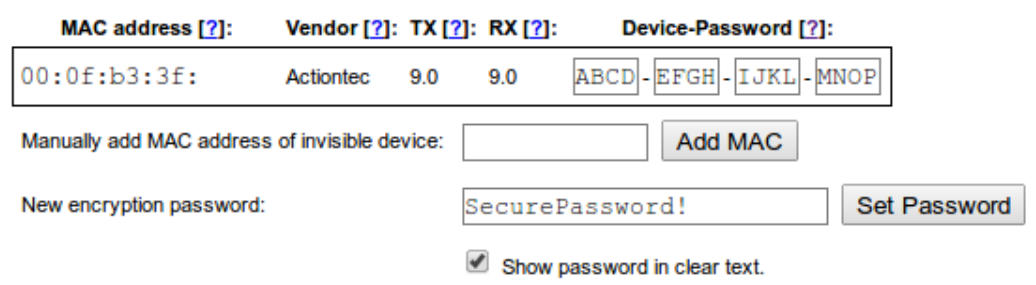
An eGauge paired with a single HomePlug adapter. Note the Encryption Key is not the factory default

An eGauge paired with a HomePlug and another eGauge meter. Again, note the non-default Encryption Key.
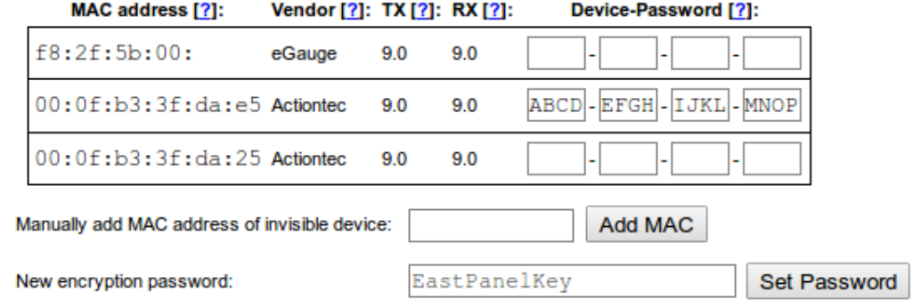
An eGauge paired with a HomePlug adapter at a location with two HomePlugs and two eGauges, preventing a HomePlug loop.
Recovering an Orphaned Device
It's possible that a device (EG301x or HomePlug adapter) may have an unknown HomePlug encryption key, and no method of reverting to the factory default key. These are referred to as "orphaned" devices, as they can no longer connect to any HomePlug network in their current state. There are two ways to recover orphaned adapters: via the eGauge UI, or via software utilities provided by the HomePlug manufacturer.
Via eGauge UI
It's possible to use the UI pairing process to set the device back to the factory standard HomePlug encryption key. Note that this process can be used for eGauge meters and HomePlug adapters.
This process is only necessary for orphaned EG301x or eGauge2 meters. For orphaned EG41xx meters, simply use the LCD interface to reset the HomePlug password, as outlined here.
To begin, make a note of the MAC address and Device ID (or DEK, PWD, etc) for the orphaned device. Make sure the orphaned device is reinstalled, powered on, and within range (about 100' of wiring distance).
1. Connect to the eGauge meter
3. A list of devices will appear. Ignore the list for now, and look for the "Manually enter MAC address of invisible device" field.
4. Enter the MAC address of the orphaned device. MAC addresses should be entered without colons (:).
5. Click "Add MAC". A new entry for the orphaned device will appear in the list of devices.
6. In the list of devices, locate the manually-added device (the Vendor column will list it as <manual>). Enter the Device ID (or DEK, PWD, etc) for that device.
7. Choose a new password (encryption key) for the HomePlug network. Remember the default is HomePlugAV - if you use the default key, any HomePlug device will be able to connect to the network. This is probably desired when rescuing an orphaned device.
8. Click "Save" at the bottom of the page and enter your credentials. The pairing process may take up to 30 seconds. If the process was successful, a confirmation message will appear. If the process was unsuccessful, an error message will appear and no changes will be made.
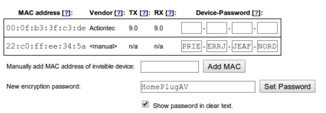
Example of an orphaned device recovery in process. Note the Encryption Password is set to the default value.
Via Vendor Software
The software below is not written or maintained by eGauge Systems. No guarantee is made regarding functionality. When using a third party adapter, it may be necessary to obtain the correct software from that adapter's manufacturer.
For HomePlug AV adapters from TP-Link, the software located at the following link may be used. For issues with the software, contact TP-Link directly.
https://www.tp-link.com/us/support/download/tl-pa2010/#Utility
What are some causes of HomePlug communication issues?
Note that a combination of the issues below may be involved with any communication problem. Also, there may be factors impacting eGauge/HomePlug communication not presented below.
GFCI Outlets
Almost all GFCI outlets will cause issues, but will not necessarily prevent communication. A standard outlet can be installed; however this may not be allowed by code. GFCI outlets which exist at the head of a chain (closest outlet to the electrical panel) will affect all other outlets on that chain.
AFCI Breakers
Some arc-fault breakers will trip when the HomePlug is connected. As of right now, eGauge Systems has no data on which breaker models have this issue. If you come across a model that causes issues, please contact the support department at support@egauge.net. Note that AFCI issues can be intermittent - for example, the breakers may trip consistently for a period, then not trip for several days, then start tripping again, with no changes to the hardware or site conditions.
Surge Protectors
Outlet-style and strip-style both cause significant issues with HomePlug communication by filtering out the HomePlug signal. More information is available here.
Phase Mixups
The eGauge communicates with the HomePlug over the phase connected to L1. If the HomePlug is installed on the phase connected to L2, it can cause significant communication issues. For more information, refer to the phasing document available here.
Transformers
In almost all cases, transformers will completely filter the HomePlug signal, resulting in a total loss of communication.
Wire Run Length
The effective range of HomePlug communications is approximately 50-100ft. Note that this distance refers to the length of wire in the walls, not a straight line between the eGauge and HomePlug. Longer wire runs will cause communication problems.
Other HomePlug Devices
Depending on the model, the eGauge either uses the HomePlug AV or HomePlug 1.0 communication protocol. Other devices using the same protocol can cause communication issues. Devices using the 1.0 protocol will not interfere with devices using the AV protocol, and vice versa. Pairing the eGauge and HomePlug together can often resolve these issues. Information on pairing the eGauge and HomePlug can be found here.
LED Codes
The color and pattern of the LEDs on the eGauge and HomePlug can help troubleshoot communication issues. A guide to the HomePlug LED codes can be found here. A guide to the eGauge LED codes can be found here (eGauge2 and EG30xx only). A guide to the EG4xxx LCD can be found here.
Out of Date Firmware
There are certain types of communication issues associated with older firmware versions. Keeping the eGauge firmware up to date is recommended. If you are unsure about the firmware version your device is using, refer to the instructions on checking firmware version located here.
Different Encryption Keys
HomePlug adapters and meters can have a unique encryption key set. If the HomePlug adapter and eGauge meter have different HomePlug encryption keys, they will be unable to communicate. By default all EG4xxx meters and compatible HomePlug AV adapters use the same default encryption key of "HomePlugAV". EG30xx meters also use "HomePlugAV", while legacy eGauge2 model meters use an older, no longer available HomePlug version that uses an encryption key of "HomePlug". See this article on changing the encryption key and pairing eGauge and HomePlug adapters.
How do I check HomePlug communication speed?
If the eGauge interface can be accessed, it is possible to view the HomePlug communication speed. Navigate to Settings -> HomePlug or use this link: http://DEVNAME.egaug.es/settings.html?s=HomePlug (replacing DEVNAME with the device name of your eGauge). This will show the transmission speed (TX) and receiving speed (RX) of any HomePlug devices within range of the eGauge (including other eGauge meters and third party products also using PLC communication). The page refreshes every ten seconds.

Sample HomePlug Communication Speed Readout
Ideally, the HomePlug communication speed should be above 2.0Mbps for both TX and RX. A speed of 9.0Mbps is the upper limit for communication speed. Speeds below 2.0Mbps can result in connectivity issues and timeouts when attempting to view data on the eGauge. Note that the RX speed will show as N/A on older eGauge2 models.
EG41xx meters utilizing the Go Proxy after January 2024 can display this information using: https://DEVNAME.egauge.io/settings.html?s=HomePlug
EG42xx Wifi Connection
You'll need either a Wi-Fi enabled laptop computer or cell phone/tablet to complete this process. Make sure your computer is not using any other network connection such as Ethernet before beginning.
Connecting the EG42xx meter to a Wifi Network
After powering the eGauge meter and making sure the included WiFi antenna is securely screwed into place on the antenna connector, press the LCD multi switch to display the Main Menu. The multiswitch can be pressed to make a selection or moved from side to side to move the on-screen highlight cursor.
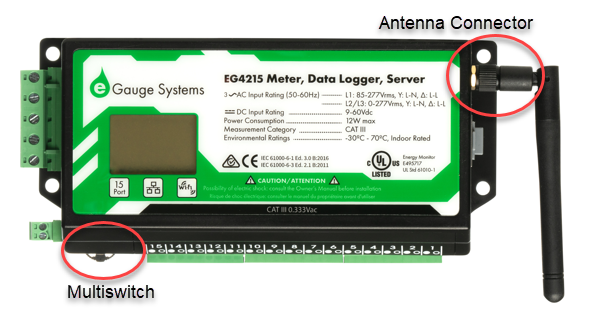
Move the switch to highlight Settings and press to enter the settings menu.

Move the switch to highlight Wireless and press to enter the wireless settings menu.

Move the switch to highlight Setup via AP and press to activate the eGauge Access Point.

The AP will remain active for 60 minutes (3600 seconds). If you wait longer than this time frame to connect, you'll need to repeat the previous steps to reactivate the AP.

Use your laptop or mobile device Wifi connection to connect to the AP displayed on the eGauge LCD screen.
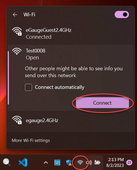
After you connect to the eGauge Wifi AP, your browser should launch automatically showing the device login screen. Enter the owner account login credentials found on the label affixed to the side of your meter, and click Sign in.
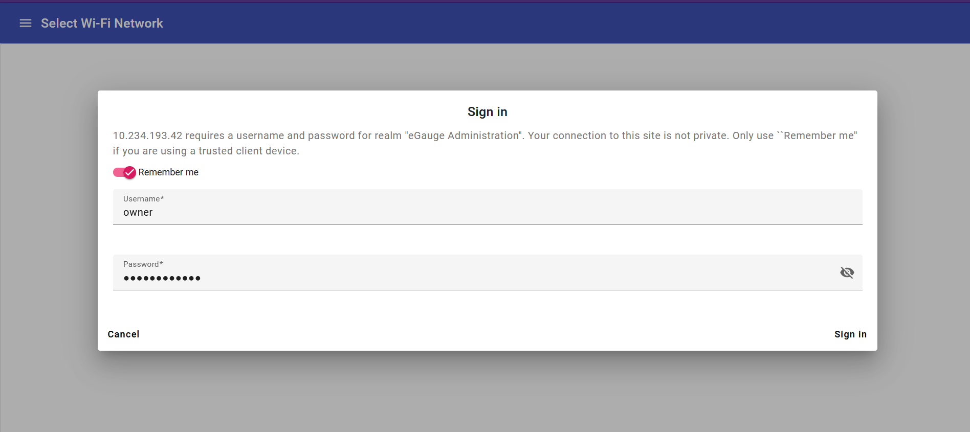
Additional step only for Samsung mobile devices
When connecting to the eGauge AP with a Samsung device, the browser will not launch automatically as it does with other devices. After connecting to the eGauge AP via Wifi, click the 'Settings' icon next to the network name., then click on Manage Router. You may then move on to the next steps.
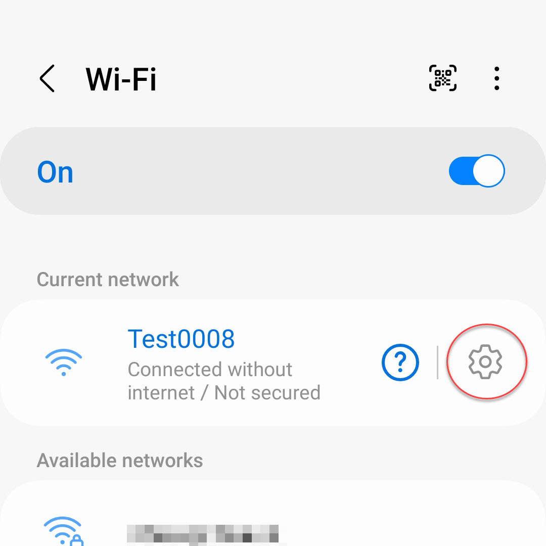
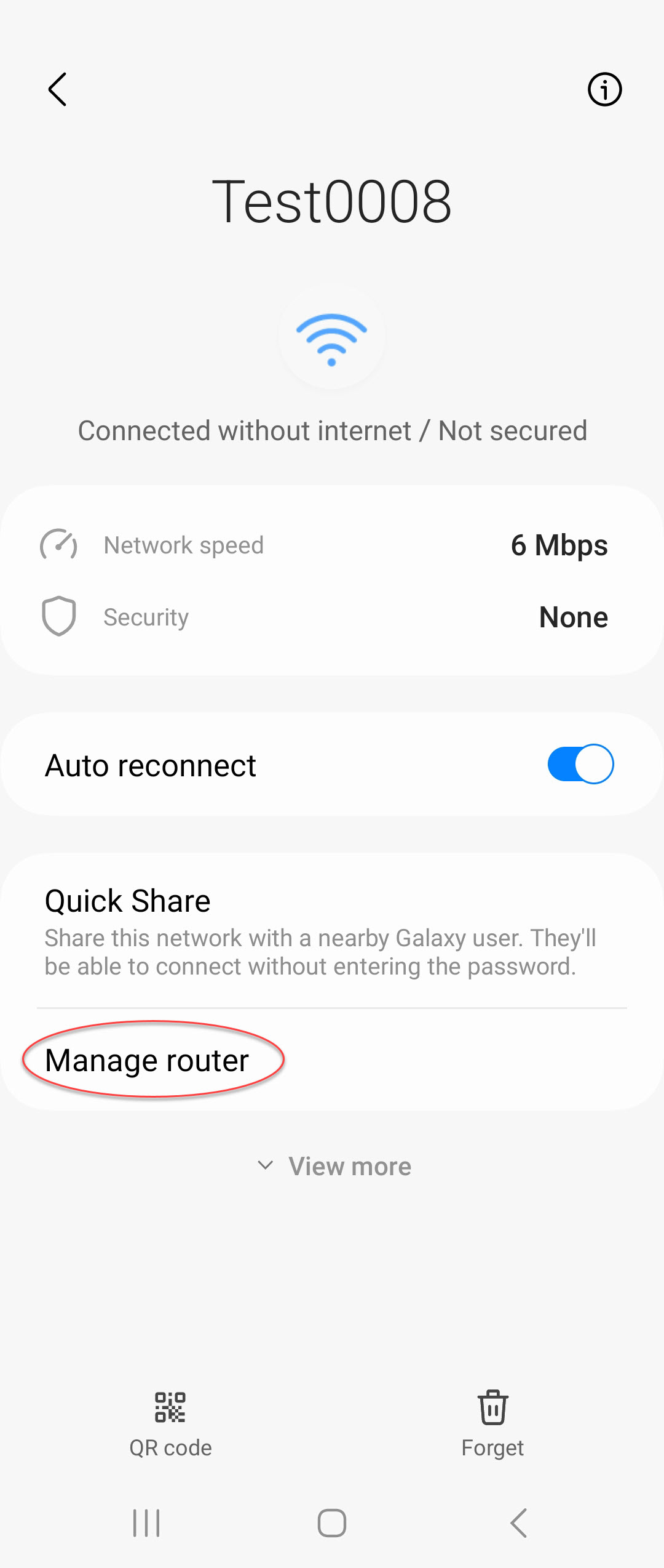
If the 'Manage Router' option is not available on your device, you can follow the steps linked here, or attempt to connect to the eGauge by opening your browser and entering the IP address: 10.234.193.42
If you don't plan to connect the eGauge to a Wifi network at this time and would like to continue with configuring the meter, click on the Main menu button in the upper Left of the screen and choose Setup >> Other Settings, then continue with the configuration process.
After logging in you will have the opportunity to connect the meter to an available Wifi network. Click to choose your preferred network and enter the Wifi network credentials and click Save to connect.
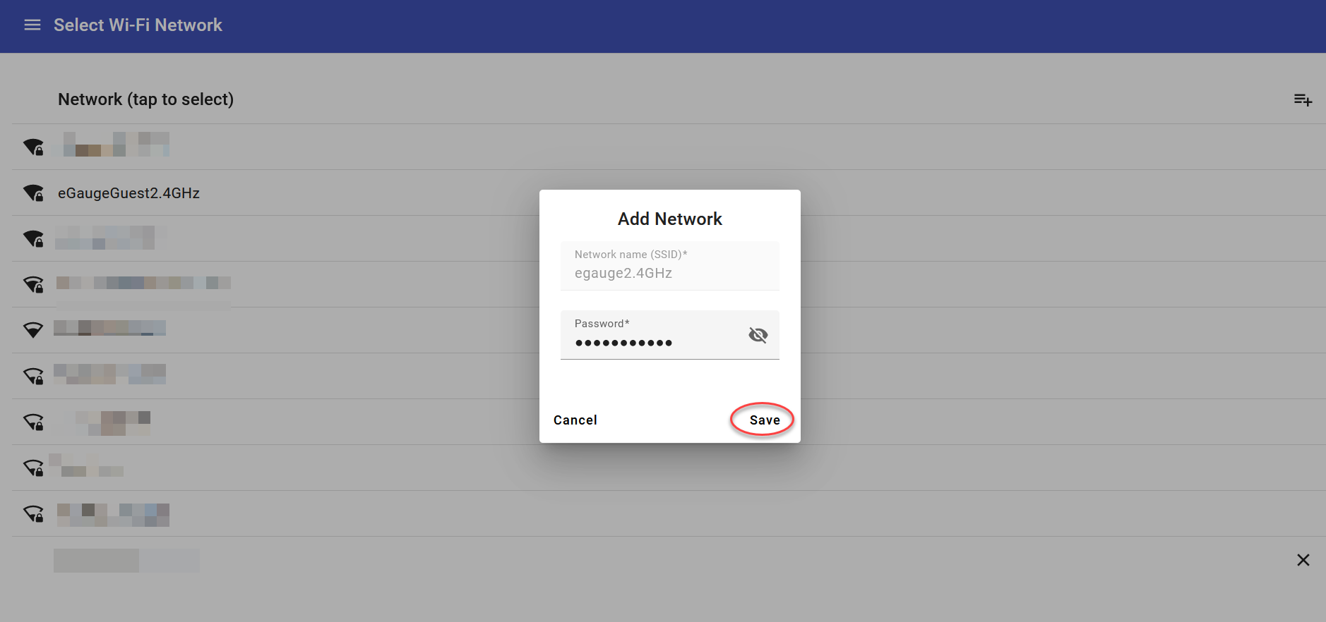
Click OK to connect to the local Wifi network, or click Cancel to go back and choose another network. When the eGauge connects to the local Wifi network, the AP function will end and you will lose connectivity to the meter. Check the eGauge LCD screen for progress.
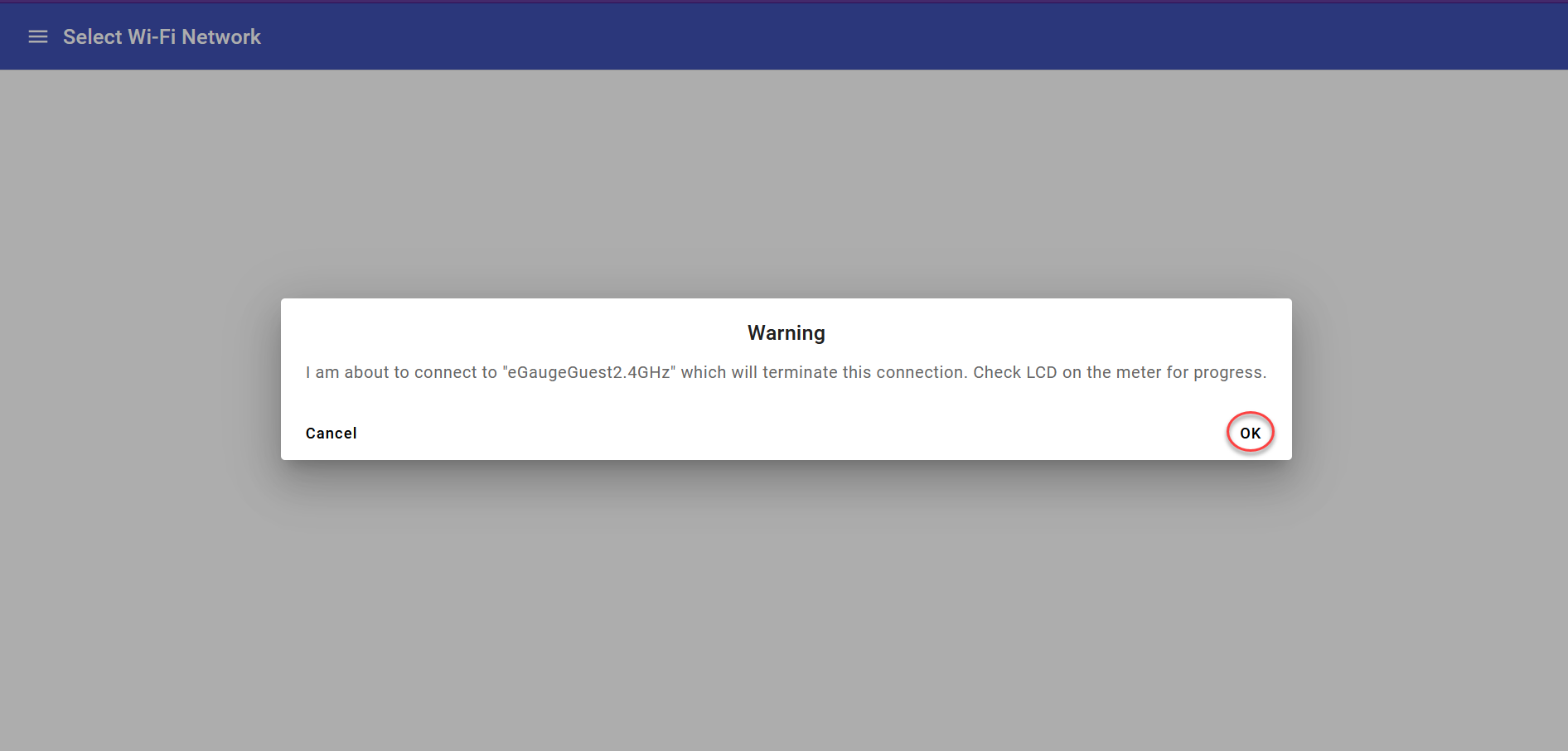
You should now be able to connect to the device via its eGauge proxy URL or at its local IP address on the LAN and continue with the configuration process.
Network Connections
The eGauge meter can be connected to a users TCP/IP network using Ethernet, HomePlug, or WiFi communication (although these connections are not required, they grant increased functionality and the ability to view the meter remotely). Related articles are found at the bottom of this page.
The eGauge listens for incoming connections from the local network for the following services:
- HTTP Web service (TCP port 80): This provides the normal user interface to access and manage the eGauge device. If desired, this port could be exposed to the Internet through a suitable firewall rule (e.g., a rulewhich forwards accesses to port 8080 to the eGauge device at port 80). The proxy service allows this service to be accessed remotely normally without requiring changes to the local network firewall or router.
- HTTPS Web service (TCP port 443) [not supported on eGauge2 or EG30xx models]: This provides secured access to the eGauge device's web server interface.
- SSH service (TCP and UDP port 22): [disabled by default*] The secure-shell (SSH) service is used for factory maintenance and servicing only and is protected by a unique password only known to the manufacturer. This port should not be exposed to the internet unless requested by eGauge Systems for advanced troubleshooting. *This service has been disabled by default starting in firmware v3.02.
- mDNS service (UDP port 5353) : The multi-cast domain name service (mDNS) makes it possible to access the eGauge interface via the local network by accessing http://devname.local/ or http://devname/, where devname is the eGauge device name. The mDNS service may also be known as "Avahi" or "Bonjour" on some operating systems.
- BACnet IP service (UDP port 47808): [disabled by default]: The Building Automation and Control network service can be enabled in Settings -> BACnet. If enabled, the eGauge will listen for BACnet master requests on UDP port 47808.
- Modbus TCP service (TCP port 502*): [disabled by default]: The Modbus TCP service can be enabled in Settings -> Modbus Server. If enabled, the eGauge will listen on for Modbus master requests on TCP port 502. *The TCP port can be changed by the user in the appropriate menu.
The eGauge maintains the following outbound connections to the internet:
- Classic HTTP Proxy server connection (TCP port 8082): The eGauge will attempt to establish and maintain a connection to the proxy server configured in Settings -> General Settings -> Proxy-server hostname. This provides web server access to the eGauge's interface via the proxy server URL, for example, http://DEVNAME.egaug.es/ or http://DEVNAME.d.egauge.net/ where DEVNAME is your eGauge device name. This connection can be disabled by configuring the Proxy-server hostname setting to the number 0 (zero). This connection is not used on EG4xxx starting in firmware v4.0.
- Classic HTTPS Proxy server connection (TCP port 8084) [unavailable on eGauge2 or EG30xx models]: The same as the HTTP Proxy server connection, but encrypted. NOTE: this is required for proxy-server connectivity on EG4xxx models starting in firmware v4.0. This connection can be disabled by configuring the Proxy-server hostname setting to the number 0 (zero).
- NTP time synchronization (UDP port 123*): The eGauge utilizes the NTP service for time synchronization. By default, servers are determined by querying {0..3}.north-america.pool.ntp.org which expands to 0.north-america.pool.ntp.org, 1.north-america.pool.ntp.org, 2.north-america.pool.ntp.org, and 3.north-america.pool.ntp.org. This can be configured in Settings -> Date & Time -> Time-server (NTP) hostname. *eGauge2 and EG30xx model devices uses the standard NTP protocol which required bidirectional UDP port 123, while newer model eGauges use the OpenNTP service which is backwards compatible with standard NTP, but can use a random high-numbered port on the client.
- eGauge.io server connection (TCP port 8084): Introduced on EG4xxx meters starting in firmware v4.4, egauge.io is a new version of the proxy client intended to replace the "Classic HTTPS" proxy server. This connection is independent of the Classic proxy server connections. When enabled and connected, egauge.io allows meters to connect to proxy.egauge.io and be accessible at https://DEVNAME.egauge.io. This connection can be configured using the JSON WebAPI under /config/net/goproxy as well as through the Modern Interface in Setup -> Network -> Proxy Server. The egauge.io connection is only supported for EG4xxx meters and not available on legacy meters such as EG30xx and eGauge2.
eGauge.io currently runs in tandem with the classic proxy server. The classic proxy-server is still the primary and recommended method for accessing eGauge2, and EG3xxx meters. Meters shipped after January 1, 2024 will automatically default to the eGauge.io proxy. For information regarding switching your EG4xxx meter sold prior to the start of 2024 to eGauge.io please see: eGauge.io Service
Other External resources
- Firmware upgrades: When a firmware upgrade is performed on a device, the eGauge downloads the signed firmware file via HTTP call to egauge.net. Some firmware versions allow firmware to be uploaded from the browser rather than downloaded from the egauge.net server.
- Dynamic resources: Some content on the eGauge may need to updated more often than firmware releases are performed. Currently, this is limited to the list populated in Settings -> Data Sharing. When these dynamic resources are required, the eGauge makes an HTTP call to egauge.net to gather this information.
- Content delivery network: When accessing newer features of the eGauge (such as the waveform view) through the proxy-server connection, the interface may have the browser request JavaScript and other resources from a separate eGauge server if it will load faster than having the data come from the eGauge through the proxy server.
- The eGauge by default uses DHCP. If the eGauge is unable to obtain a DHCP address, it will default to 192.168.1.88. It will continue to request a DHCP address and will obtain one when the service is available. It should not take more than 15 minutes to obtain an IP after the server is available. A static IP may be configured in Settings -> Network Settings.
Related Articles
eGauge Proxy Server Security and Functionality
HomePlug Security Considerations
eGauge Proxy Server Security and Functionality
All metering data is stored locally on the meter hardware itself, the proxy server only acts as a relay between the internet and local meter interface to serve data remotely. The meter will have full functionality and no reduction in capacity if the meter is not connected to the eGauge proxy server or even the internet in general.
Accessing the meter via local network IP or hostname will show the same web interface as if visiting using the eGauge proxy server, for example https://eGaugeHQ.d.egauge.net or https://eGaugeHQ.egaug.es will show the same thing as if you were on the local network visiting the meter via IP address, such as https://192.168.1.102. For local IP or hostname access to work, you must be on the same local network as the meter.
egaug.es is an alias of d.egauge.net and may be used interchangeably.
Encrypted connections are supported on EG4xxx series meters. Legacy meters, such as the EG30xx and eGauge2 do not support an encrypted connection between the meter and proxy-server. However, if encryption is supported by the client browser, encrypted HTTPS may be used between the proxy-server URL and the client browser.
To disable the eGauge proxy server, navigate to Settings -> General Settings and set "Proxy-server hostname" to the number 0. In this case, support services may be limited due to the meter not being available for remote troubleshooting and assistance.
Overview

The eGauge proxy server allows easy remote access to the eGauge webserver interface. Because the connection is established outbound from the device, usually no changes to the router or firewall are necessary.
The proxy server relays data stored on the eGauge meter to the client browser requesting it, and keeps the meter location and IP address anonymous. The client browser will see data coming from the eGauge proxy server, not the IP address of the eGauge device. All communication via the proxy is handled by the proxy, the client browser never directly communicates to the eGauge meter.
When an eGauge device is powered up, it connects to port 8082 (eGauge2/EG30xx, non-encrypted) and 8084 (EG4xxx, TLS 1.2 encrypted) of the server defined in the under Settings -> General Settings -> Proxy-server hostname. Normally, this is set to d.egauge.net but may be different for certain customers.
If the connection is successful, the device will be available remotely at http://DEVNAME.PROXY (and https://DEVNAME.PROXY/ if EG4xxx model or newer) where DEVNAME is the eGauge device name and PROXY is the proxy-server hostname. For example, http://eGauge99999.d.egauge.net (or http://eGauge9999.egaug.es, as "egaug.es" is an alias for d.egauge.net).
If a device does not have a site-wide password enabled and is connected to d.egauge.net, it will become visible on the "Find my Device" page at egauge.net/eguard/find/. To be removed from this list, enable a site-wide password in the eGauge interface through Settings -> Access Control -> Password-protect entire site.
Disabling the proxy-server connection
If for any reason it is undesirable to maintain the proxy-server connection, “Proxy-server hostname” under Settings -> General Settings can be set to "0" (the number zero, without any quotes). Once this setting is saved and the device restarted, it will only be possible to connect to the eGauge device from the LAN or with port-forwarding configured on the router/firewall.
Security Considerations
If an eGauge device is available on the proxy server, anyone with the URL can attempt to access. If meter data is intended to be private, a site-wide password should be enabled as described in the previous section.
If remote administration is enabled on a user account ("Allowed to view all data and change settings from anywhere" access in Settings -> Access Control), the password must be secure enough to prevent brute-force attempts at cracking the password.
The proxy server uses a combination of hostname and private-public key authentication when meters connect. This ensures it is not possible for meters to be renamed and "overlap" with another, and ensures any connections to the proxy are authorized and commissioned by eGauge Systems.
HTTPS Access
It is recommended to use up-to-date firmware as there are periodic releases with enhancements and bug fixes. Information on upgrading meter firmware can be found here.
The current line of meters (EG4xxx) support HTTPS access locally and via the proxy server.
Data transferred between EG4xxx meters and the proxy server are encrypted using TLS 1.2, and data between the web browser and proxy server is encrypted using TLS 1.3.
Local webserver access to EG4xxx provide TLS 1.2. EG4xxx meters can use a custom SSL certificate as well.
Local insecure HTTP access may be disabled via Settings -> Network Settings -> Disable unencrypted network services.
Legacy Model Meters
Legacy meters (eGauge2, EG30xx models) do not have encryption (HTTPS) available via the proxy server. Care should be taken when configuring passwords to ensure the local internet connection is not compromised. Credentials when used to save settings are not transmitted over plaintext or reversible as they use HTTP digest authentication.
Related Articles:
Configuring a remote eGauge
Best practice is to set up all the registers on all devices before attempting to pull registers from the secondary eGauge(s) to the main eGauge. Adding and importing registers after the initial configuration will not retroactively import data for those registers.
1. Determine which eGauge should be the main device. Ideally, this will be the device with the best network connection (hard wired with Ethernet is preferable) and the greatest number of registers (this means that it has to pull in fewer registers from the remote device, which saves on network overhead).

eGauge Remote Devices field - partially completed
3. Click the "Edit" button on the far right. This will allow you to change the communication protocol using the drop down menu and enter the device address. The two protocols supported by the eGauge are "remote eGauge via UDP" or "remote eGauge via TCP". Use the UDP option when the devices are on the same network (connected to the same router). When the devices are located on different networks or as a backup when UDP will not connect, use the TCP option.
4. Next, enter the device address. For an eGauge using UDP, it is simply the device name (for example, egauge12345). For an eGauge using TCP, you will need the whole address (for example, egauge12345.egaug.es). Do not include "http://" or "www." at the start of the address.
Remote eGauge meters using TCP because they are geographically separated will be more prone to accumulating excess due to more uncertain network conditions than meters communicating on the same LAN over UDP. For more information on what excess is, see: What is Excess?
5. Now, attempt to fetch registers from the device. Click on the grey question mark "?" between the "Device address" field and "Edit" button. After a few seconds, this should turn into a green check mark. If it turns into a red "X", the remote device is offline, the address is entered incorrectly, or a connection cannot be established.

Green check mark
6. Once you obtain a green check mark, you need to import specific registers. To do so, click "Add Registers" under the Registers: header. Name the register whatever is appropriate, then click on the drop down menu containing the letter "P". Select your remote device's device name from this menu. Another menu will appear to the right; from here you can select the register you wish to import. You must create a new register on the main eGauge for each register you wish to import.

Example of registers imported from a remote device
7. After you have added all the registers you wish to record on the main eGauge, click "Save" at the bottom of the screen. You may be asked for your username and password.
One final note: if you navigate away from the installation page, you will need to repeat step 5 in order to fetch additional registers.
Configuring a USB WiFi dongle
The EG4xxx, with an attached supported USB WiFi dongle, can be configured to connect to a WiFi network. There are two methods of connecting the eGauge to a WiFi network.
WPS push-button pairing.
The EG4xxx LCD screen has the ability to pair to a WiFi network using WPS push-button pairing. To push-button pair the eGauge with a compatible WiFi router:
1) Initiate the WPS pairing process on the wireless router. Often, this is done by holding a button on the back of the router for 1 to 10 seconds. Consult your router documentation for more information on whether it is available and how to perform it. Do not push any buttons on the wireless router without consulting the manual first, as it's possible a push-button action can cause a factory reset which may lead to internet loss!
2) Initiate the WPS pairing process on the EG4xxx LCD screen by navigating to Settings -> Wireless -> WPS Setup. When successful, the LCD screen will indicate the network it paired with.
Manually entering SSID and password.
1) Obtain the SSID (wireless network name) and password from the administrator. Note the SSID and password are case-sensitive, so it is important to verify the exact WiFi network name and password.
2) Connect to the eGauge interface either over a local area network or directly connected via Ethernet.
 |
 |
4) Once connected, the wireless network will appear highlighted in green.

Comparison of Communication Options
EG41xx meters with built-in HomePlug communication have been discontinued. If HomePlug communication is required on an EG40xx, one HomePlug adapter may be connected to the eGauge meter's Ethernet port and the other may be connected to the router or modem as in a normal EG41xx setup using HomePlugs.
Overview
The eGauge meter is a flexible piece of hardware. For most use cases bandwidth requirements are quite low (a 500 Kbps connection is the minimum for a good user experience, but the eGauge will function on connections as slow as 128 Kbps). The eGauge can take advantage of many connection types, including direct Ethernet, powerline communication (PLC), WiFi, cellular, and even more exotic hardware such as point to point antennas. As a general rule, if a connection is adequate for a "standard" computing device such as a desktop or laptop computer, the connection will also work with the eGauge meter.
However, there are some pros and cons to various communications options. This article will cover some of the common communications options used with the eGauge meter, with links to hardware supported by eGauge Systems (if applicable). Note that unsupported products may be used, but eGauge Systems cannot guarantee compatibility or functionality of unsupported products.
The eGauge meter will store data even without an active internet connection, although this data will not be visible remotely when the meter is not connected to the internet.
Table of Contents
eGauge Meter Capabilities
Ethernet
HomePlug (PLC)
WiFi
Cellular
eGauge Meter Capabilities
There are several eGauge hardware revisions, and each revision contains multiple models with different communication options. The following table illustrates the various meter models and built-in communication options. Note that an Ethernet port can be used to connect other devices (such as a WiFi bridge or cellular modem).
| Meter Model | Ethernet | WiFi |
HomePlug (PLC) |
| EG4230 |
X |
X |
|
| EG4215 |
X |
X |
|
| EG4030 | X | ||
| EG4015 | X | ||
| EG4130 (discontinued) | X | X (HomePlug AV) |
|
| EG4115 (discontinued) | X | X (HomePlug AV) |
|
| EG301x (discontinued) | X | X (HomePlug AV) |
|
| EG300x (discontinued) | X | ||
| eGauge2 (discontinued) | X (HomePlug 1.0) |
Ethernet
Every eGauge meter currently in production has an Ethernet port, which allows the meter to be connected directly to the customer's network. Ethernet has a distance limit of about 330'/100m. Repeaters can be used to extend this distance in some cases.
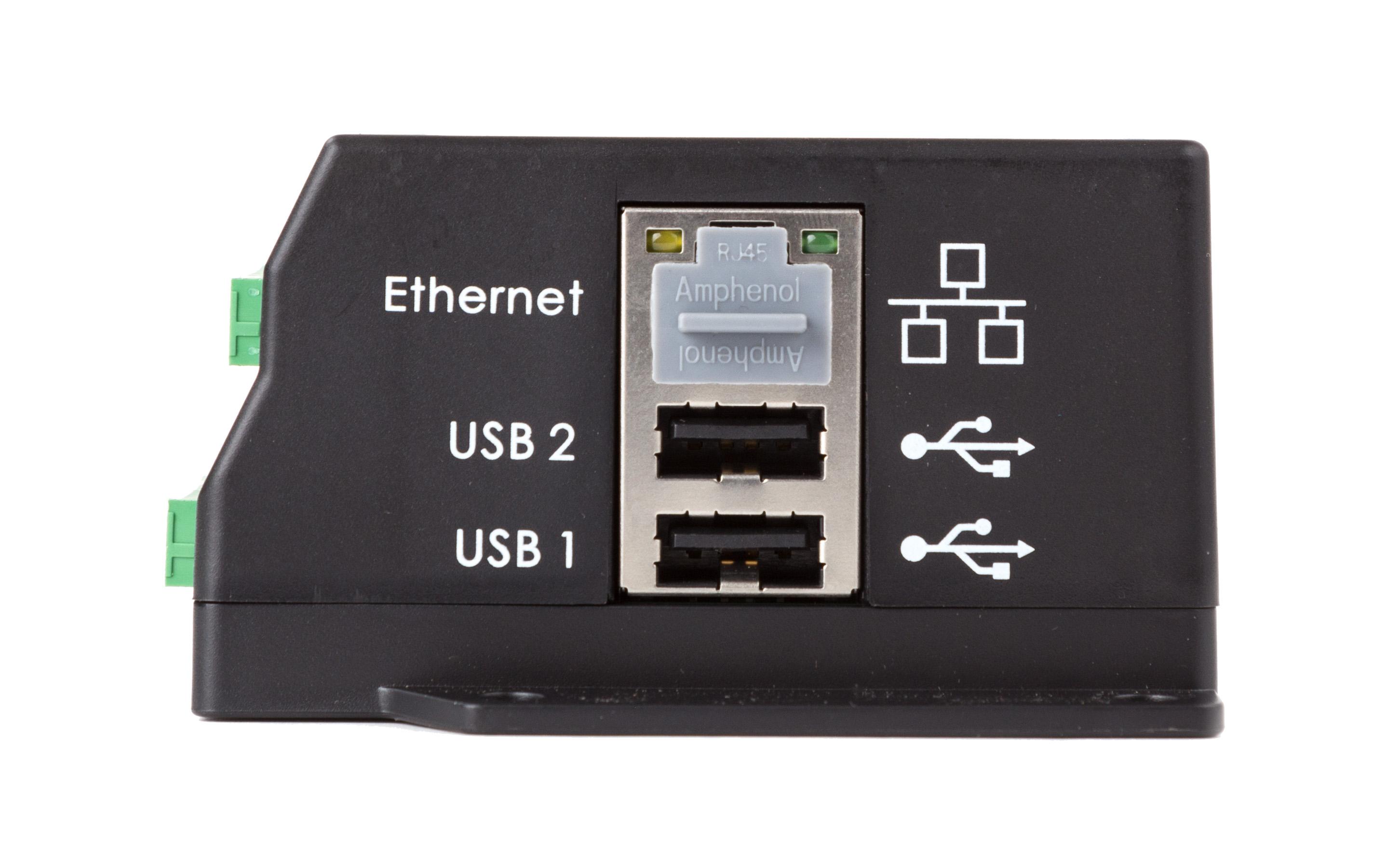
EG4130 meter showing Ethernet port (covered with grey protective plug)
An Ethernet connection between the eGauge and the customer's existing network (router or switch) is the most reliable and robust communication option. A wired connection reduces the risk of communication issues due to network changes (such as setting a new password on a WiFi network) or local interference. Ethernet can also be expensive to run, although the cost of running Ethernet is often offset by reduced costs for site visits or troubleshooting time over the life of the meter. A direct Ethernet connection is generally the fastest connection type, although a single meter won't see any substantial benefit from speeds over about 5Mbps. In many cases, a single Ethernet run can support multiple eGauge meters when a powered unmanaged switch is used.
In more secure locations such as hospitals or banks, it may not be possible to connect the eGauge to the customer's network due to network usage restrictions on the customer's end (e.g., only "approved" devices may be connected). Specialized installation and testing tools are generally required for Ethernet installations. It also may be necessary to run the Ethernet cable in suitable conduit depending on code requirements. Ethernet cabling and conduit in large quantities can be expensive, and in residential locations extensive rework may be required to accommodate Ethernet runs.
| Pros | Cons |
| Most stable and reliable, very fast speeds | Expensive to run, requires special tools |
| Reduce future troubleshooting/support costs | May not be allowed based on network policy |
WiFi
EG42xx model eGauge meters have built-in 2.4 GHz WiFi communication which allows the eGauge meter to connect to nearby 2.4 GHz WiFi networks. WiFi enabled models have an external RP-SMA connector to allow use of the included 3'' antenna or a custom high-gain directional antenna for point-to-point connectivity.
WiFi-enabled eGauge meters also have a "Setup via AP" mode which allows the eGauge to broadcast a wireless network for a one-hour duration to allow initial setup and connection to an existing WiFi network, as well as general use such as temporarily downloading data wirelessly when there is no local network available.
| Pros | Cons |
| No additional Ethernet or power wiring required |
May not be usable depending on quality of WiFi coverage |
WiFi (external module)
The EG42xx model meters have built-in WiFi with a larger operating temperature range than external modules such as the AP-WR802N.
The eGauge can be used with a WiFi bridge connected to the Ethernet port, which will allow the eGauge to connect to nearby WiFi networks. eGauge Systems officially supports the AP-WR802N, which can be powered from a USB port and is generally suitable for short distances and residential/small commercial applications. Unsupported WiFi bridges (including directional antennas) may be used, but it may be necessary to obtain configuration assistance from the manufacturer directly - eGauge Systems cannot help with configuration of third party WiFi devices. It is recommended to use the 2.4GHz band whenever possible, as 2.4Ghz has better penetration characteristics and the eGauge can't take advantage of the speeds offered by the 5GHz band.
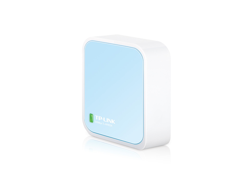
TP-Link AP-WR802N WiFi bridge. The Ethernet and USB (power) ports are not shown.
Like HomePlug, a WiFi bridge doesn't require any additional wiring to be run between the customer's router/switch and the eGauge, which can reduce initial costs. WiFi bridges are also relatively inexpensive. Some WiFi bridges feature external antennas which can be extended to get the best signal without relocating the bridge itself.
However, WiFi adapters require some configuration and testing, which means they're not as easy to install as a HomePlug adapter. 2.4Ghz WiFi adapters have a maximum range of about 150'/45m indoors, but they may need to be positioned in a specific location to get a good signal. In certain areas (for example, mechanical rooms with lots of conduit and wire in the walls, or block/brick/concrete structures), the WiFi signal may be poor or nonexistent, even if the router is nearby. WiFi signal may be degraded or eliminated by nearby sources of electromagnetic interference. Changing the password or SSID of the WiFi network will require the end user to update the configuration on the WiFi bridge, which may be difficult if the bridge is in a hard to reach location.
| Pros | Cons |
| Relatively inexpensive |
Requires initial configuration and testing |
| Moderate to fast speeds |
May not be usable depending on quality of WiFi coverage |
| Can be installed near the eGauge | Must be reconfigured when network settings are changed |
| Can be used in most commercial/industrial settings | Even under ideal conditions, connection may not be stable |
Cellular
The eGauge can be connected directly to a cellular modem with TCP/IPv4 networking capabilities (DHCP is optional, but preferred for ease of use). Currently, eGauge Systems supports one cellular modem: the InHand IR615. This cell modem has built-in routing capabilities and can share a connection with up to four eGauge meters. Using a switch or similar networking hardware allows the modem to support additional eGauge meters.
InHand cellular modems (the model offered may change over time). The antennas are not shown.
The cellular modem requires a dedicated power supply and an active data plan. eGauge Systems offers and supports data plans from T-Mobile, but for other carriers it will be necessary to work with the carrier and modem manufacturer to configure the modem correctly. Other modems can generally be used if they also function as routers, but this is not officially supported. Take care when using data plans not offered by eGauge Systems - other data plans may charge for data overages, so unlimited data plans are highly recommended.
Like HomePlug, a cellular modem doesn't require any additional wiring to be run between the customer's router/switch and the eGauge, which can reduce initial installation costs. Since the cellular modem is essentially a dedicated network with no ability to access the customer's local network, it may be better suited for high security locations where local network access isn't available. A cellular connection removes reliance on the quality and uptime of the customer's network, which may reduce troubleshooting costs. Cellular modems are also well suited for many rural or remote locations or areas where traditional wired internet isn't available or is prohibitively expensive. Most cellular modems feature external antennas, which can be extended to find the best signal without moving the modem itself.
However, cellular modems are more expensive compared to a communication technology which uses the customer's existing network, such as HomePlug or WiFi (with a cellular modem, you're essentially building a second dedicated network for the eGauge). They also require an active data plan (typically an ongoing monthly cost). Like WiFi bridges, cellular modems are prone to communication issues due to poor or nonexistent coverage. The modems ship preconfigured, but may require additional testing to function properly (or additional configuration to use with a different carrier). In certain areas (inside metal/block/concrete buildings, underground etc) a cellular signal may not be available. Cellular signals can be degraded or blocked by external factors, such as inclement weather, power outages, etc. Cellular towers are owned and maintained by cellular providers, who may decide to remove or decommission a tower with no notice. This may leave a site without an active cellular connection.
| Pros | Cons |
| Usable where local network access isn't available | Subject to a variety of external influences |
| A single InHand modem can support 2 eGauge meters (more if an external switch is used) | Coverage not guaranteed |
| Suitable for high-security locations | Expensive, with ongoing fees |
| May require additional configuration or testing |
HomePlug (PLC)
EG41xx meters with built-in HomePlug communication have been discontinued. If HomePlug communication is required on an EG40xx, one HomePlug adapter may be connected to the eGauge meter's Ethernet port and the other may be connected to the router or modem as in a normal EG41xx setup using HomePlugs.
HomePlug is a powerline communication (PLC) standard used to convert data from an Ethernet line into a form which can be transmitted over the electrical wiring of a building. In a typical installation, a HomePlug adapter is placed near the customer's router and connected to the router via an included Ethernet cable. The adapter then establishes a link to the internal HomePlug adapter built into certain eGauge models. Optionally, the HomePlug adapter may be paired with the eGauge to increase security.
TRENDnet HomePlug Adapter. Note that HomePlug adapters differ based on manufacturer.
HomePlug adapters are easy to install and relatively inexpensive compared to running Ethernet in an existing structure. However, HomePlug also has some limitations. These include a relatively short range (100'/30m of wiring distance) and voltage limitations (most adapters are only rated for 120V installations, making them useless in commercial settings). External factors such as excessive noise on the electrical lines can also cause problems. In some cases, the customer may forget what the HomePlug adapter is used for and dispose of it.
HomePlug adapters are manufactured by third parties, although certain models are sold and officially supported by eGauge Systems. Unsupported models should work, but this cannot be guaranteed. A single HomePlug adapter may be used to provide a connection to multiple eGauge meters, provided all of those meters are within range.
| Pros | Cons |
| Easy to install, no special tools required | Relatively short distance |
| Relatively inexpensive | Prone to interference from a variety of sources |
| Suited to residential or small commercial applications | Unusable in larger commercial/industrial settings |
| Single adapter can serve multiple eGauge meters | May run into issues with existing HomePlug devices at site |
| Moderate to fast speeds, generally stable | May forget what the adapter is for and throw it away |
Custom HTTPS certificates (EG4xxx only)
Starting in firmware v4.2 a custom HTTPS certificate may be uploaded to the meter and used for local HTTPS webserver access. This does not affect the proxy-server access (e.g., https://eGauge9999.d.egauge.net , https://eGauge9999.egaug.es or https://egauge9999.egauge.io).
eGauge Systems cannot provide certificate files or assist with certificate generation.
Only EG4xxx model meters may be used with custom HTTP certificates.
The certificate must be a single file containing the private key and full chain and certificate in PEM format. See below for an example of how this file should look.
Installing the Certificate
From the main eGauge interface, navigate to View -> Mobile Friendly:
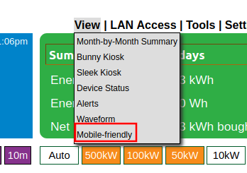
Click the hamburger menu in the upper left-hand corner and navigate to Setup -> Network -> Web-server:
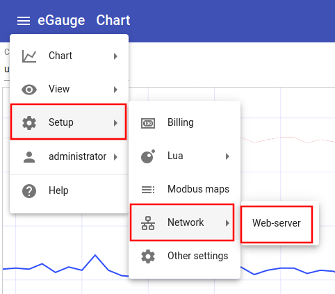
Click the "Upload" button:
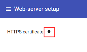
Click where it says "Filename" and choose the certificate file to upload. This must contain the private key and full chain in the same .pem file.
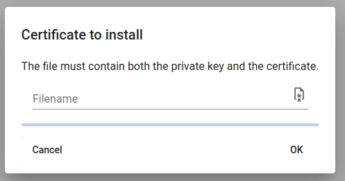
If successful, you will be redirected back to the main page and see a confirmation at the bottom of the page the certificate was updated:
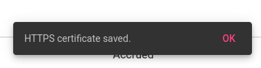
If there is a problem with the certificate file uploaded, you will receive an error message at the bottom of the screen:
If there is a failure, check the certificate file format is correct and not corrupt.
Certificate file format
The certificate file must be in .pem format and contain the private key and full chain. It should have a single BEGIN PRIVATE KEY stanza, and one or more BEGIN CERTIFICATE stanzas. For example, a certificate may look similar to this (note: this example uses random data; it will not function as a certificate).
-----BEGIN PRIVATE KEY-----
UQgbR5+plL42go05/VKtq3F24IdC5XPVJ2/X3L5cn7cvyZFCiQ58tk
4YYLwmm4b035/rg65e6YuyEDo+zxCOikMPaSeIuBWtLBKQUZw3bTyc
GtQ4FipRXBcFySDdEFuM1YuS7e8M9/h3mt5dIrJnrRA/Pa9x6gzkWz
4Ow9xbm0JgPGkfaJVX5vbauIr0UAc72MNg+lO8uuA2jH+f1fdpe4Rg
YhWKwuum4ZOjh+t5b4PgPmkSGJDR0W7w1Y55TXlxXEm=
-----END PRIVATE KEY-----
-----BEGIN CERTIFICATE-----
0QUubtUgnDnougS2OqNgoeNkeE2fGEJInSTA4hfk6AyqSWU5qS7qgF
yVcC/ixal1yjtrXoASENP5r3tQALpiFr/+PFnHS/+g2Ja7DQqYRByO
M1Za4oiLqpphyEMAB7CdXK4Etla8JbWj60XX2DLxwys9TxZR6UrsKl
ghZORWId89MaKlz5Xy1ymPy2Iz7GUASdchtWZyeOz+w+5dZvGUQ/O6
MGsIAqXO/t6UUsxfSLzyCwUlahL7FQ3Pa3XPcwPEaoaBt/II4CEzCw
DqZki2STUjCVHO/RR3vuswEClHXsyR+Pq8xnuzdnD2vSEumL7QQwf1
DnsW7IKMGkMMfDm2
-----END CERTIFICATE-----
-----BEGIN CERTIFICATE-----
UfWOH8729kTbI5GRr5N13R0Coqys4lXtboiI5o97XYLt/S5I/r49WY
3dnlKlaILurkzptNuY2PywlClib9Zkvu3ZukFusvMV2cick7NLTmim
rBOYeFGL/j7lO+jpLVLySLL9ER2tlUS+EJpI+P5qhJkudQrMDTniQm
FWcAtaD7vQ2LTYlWoJj/p5Xgfb/t7SwwGF7TS4Mq+2zRzVwcx9wm7N
ddp7zK9hWm/uw+hMG8moVAk6k+g5/LN8HmoDQDWR09WB4PPcJcLbmn
4Hy2Q8vJYRS3wBjUdy1CXZcmMS2RJLwAo6V8r4eEn5Krudbqm/hsUr
QHBRbftX/rvUGRhl
-----END CERTIFICATE-----Creating certificate file example
Most certificate services provide separate certificate and key files and the private key needs to be concatenated with the certificate. For example, Lets Encrypt as of this writing provides several files: cert.pem, chain.pem, fullchain.pem, privkey.pem, and README. The example below show obtaining a Lets Encrypt certificate and creating the pem file to upload to eGauge. The file egauge-cert.pem will contain the contents of privkey.pem followed by fullchain.pem and can be uploaded to the eGauge meter.
root@localhost:~# certbot certonly -q \
--dns-cloudflare \
--dns-cloudflare-credentials ~/.secrets/cloudflare.ini \
-d meter-name.example.com
root@localhost:~# cd /etc/letsencrypt/live/meter-name.example.com
root@localhost:/etc/letsencrypt/live/meter-name.example.com# ls
cert.pem chain.pem fullchain.pem privkey.pem README
root@localhost:/etc/letsencrypt/live/meter-name.example.com# cat privkey.pem fullchain.pem > egauge-cert.pemeGauge.io Service
What is a proxy server?
A proxy server provides remote access to an eGauge meter which may be connected behind a firewalled network. The proxy connection is initiated outbound, which in most cases allows for remote access without the trouble of configuring firewall or port forwarding rules. High-security networks and intrusion detection systems (IDS) may block unknown connections and still require firewall rules to allow the proxy service to connect.
What is eGauge.io?
eGauge Systems have launched a next-generation proxy service known as eGauge.io. The eGauge.io proxy service is available for use on all EG4xxx meters running firmware 4.5.6 or newer. Legacy meters, such as eGauge2 and EG30xx cannot utilize the eGauge.io proxy server, but will still operate with remote access on the classic d.egauge.net or egaug.es proxy server.
Geographically Distributed
The eGauge.io proxy service has multiple servers, distributed geographically across the world. The specific server used depends on the geographic location of originating IP of the meter or client browser via internet geolocation. All servers seamlessly provide web browser access to any meter, regardless of whether the browser is accessing the same server as the meter is connecting to.
For example, a meter in Germany may connect to an eGauge.io server in Frankfurt. If someone in Vermont attempts to view that meter, their browser may resolve to a closer eGauge.io server in New York. The server in New York will seamlessly relay the data from the meter connected Frankfurt.
The distributed nature of the eGauge.io service allows for the most efficient network paths and fastest response times.
Security
All connections eGauge.io servers (i.e., meter, client browser, and inter-proxy communications) are encrypted with TLS 1.3.
When a browser initates a web connection to view a meter, the IP address resolved will always be of the particular eGauge.io server that is resolved via geolocation: never the originating IP address of the meter.
Meters are authenticated using public key authentication to prevent meter spoofing. The private key is embedded in non-removable media on the physical meter and cannot be obtained.
Required Connections and Ports
Meters attempt an outbound connection to port 8084 to proxy.egauge.io to become available on the eGauge.io
server. If this connection fails for any reason, the meter continues to fully function, but will not be
available remotely via the eGauge.io proxy server.
Due to the geographically distributed nature of the eGauge.io proxy service, the IP address for proxy.egauge.io
can vary.
For information about other connections the meter may utilize, see the Network Connections article.
Disabling the eGauge.io proxy service
Disabling the eGauge.io service will revoke remote access to the eGauge meter. Restoring access can only be done by accessing the meter via local IP address or a factory reset which can result in data loss. eGauge support will have limited troubleshooting abilities if the meter is disconnected from the eGauge.io proxy service.
The eGauge.io proxy server may be disabled by navigating to Setup > Network > Proxy Server in the Modern User Interface and un-checking the box for Proxy Server Enabled.Connecting your Pro or Core meter to eGauge.io
If your eGauge meter was shipped prior to January 1, 2024 it would have been set to connect to the Classic eGauge proxy by default. If you'd like to connect your eGauge Pro or Core model meter to egauge.io you can do so by following the steps in this article. If you're not sure if your eGauge is already connected to egauge.io you can check by visiting: https://DEVNAME.egauge.io
This change must be completed in the Modern User Interface . Do not attempt to make this setting change in the Classic eGauge Interface or you will lose proxy connectivity to your eGauge device. Please note that this connection is not available for EG30xx or eGauge 2 meters.


- Make sure 'Proxy Server Enabled' is checked and set your Proxy Server Hostname as shown below:

Unix time, timestamps, and timezone information
What is Unix time?
Unix time is simply a numerical value of the number of seconds that have elapsed since January 1, 1970, midnight, UTC. This date is called Unix epoch.
Unix epoch is not to be confused with the eGauge or meter epoch, which is configured in Settings → Date & time when recording started. The meter epoch represents the time the meter was comissioned and began recording accurate data.
What is UTC?
Coordinated Universal Time (abbreviated UTC) is a standard to coordinate and identify timezone differences. When times are related to UTC, they are written in a format that indicates the offset of the local time to UTC.
For example, U.S. Eastern Standard time is 5 hours behind UTC (-5), and a timestamp that is
relative to Eastern Standard time may be written as 2023-12-22 15:30:00-05:00. This removes any
ambiguity or question of what timezone it is for, as well as whether it is Standard or Daylight
Savings Time.
Likewise, Japan Standard Time is 9 hours ahead of UTC (+9), and the same moment in the previous example
(2023-12-22 15:30:00-05:00) is the same time as2023-12-22 05:30:00+9. In UTC, the time would be
2023-12-22 20:30:00-00:00. The equivilent Unix timestamp for this is 1703277000.
What about timezone information?
As Unix timestamps use UTC, there is no concept of a timezone for a Unix timestamp. When processing Unix timestamps, you determine the human-friendly time of the Unix timestamp (which is in UTC), and then apply the desired timezone's offset.
For example, a Unix timestamp of 1703277000 is Friday, December 22, 2023 8:30:00 PM UTC. If we want to
convert that to U.S. Eastern Standard Time, which is 5 hours before UTC, we subtract 5 hours and get
Friday, December 22, 2023 3:30:00 PM UTC.
Most common programming libraries contain methods for converting Unix timestamps into human-friendly
timestamps with timezone information. For example, Python3 can use the datetime and pytz to easily convert
a Unix timestamp into a human-friendly, localized time. For example, here we are using Python3 to convert the
timestamp in our previous example to U.S. Eastern Time (pytz will automatically choose Standard or DST):
>>> from datetime import datetime
>>> import pytz
>>>
>>> tz = pytz.timezone('US/Eastern')
>>> ts = int('1703277000')
>>> print(datetime.fromtimestamp(ts,tz).strftime('%Y-%m-%d %H:%M:%S'))
2023-12-22 15:30:00
Where are Unix timestamps used?
When interacting and obtaining data from an eGauge API, BACnet, or Modbus service, timestamps and time-ranges are most often reported and requested as Unix Timestamps.
For example, the following JSON was obtained through the WebAPI. There are two Unix timestamps,
the first in the main body ("ts": "1703275428") reporting the current time of the meter that the
response was generated, and another within the ranges section ("ts": "1703030400").
The first timestamp translates to Friday, December 22, 2023 8:03:48 PM, UTC. This is the time
the response was made. The second timestamp translates to Wednesday, December 20, 2023 12:00:00 AM, UTC,
which is the timestamp for the first row's values.
{
"ts": "1703275428",
"registers": [
{
"name": "S15 A",
"type": "I",
"idx": 4,
"did": 0
}
],
"ranges": [
{
"ts": "1703030400",
"rows": [
[
"2078357324"
]
],
"delta": 0
}
]
}