Modbus
eGauge meters can read and output Modbus RTU and TCP
- Modbus Output Communication
- Sunspec Support
- Custom Modbus definitions (read from any Modbus device)
- Creating, Sharing, and Using Modbus Maps
Modbus Output Communication
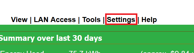
All eGauge models with firmware v3.2 or higher have Modbus TCP output capability. eGauge models with USB ports also have capability for Modbus RTU (serial via RS485) output capability, with use of the eGauge USB485 converter. The Modbus server can be enabled in Settings -> Modbus Server. If the Modbus Server option is not available, upgrade your firmware in Tools -> Firmware Upgrade.
NOTICE: Prior to firmware v4.0, the Modbus map addresses are liable to change if the register name or contents is modified. Firmware v4.0 adds additional ranges that are tied to the register ID. The addresses used prior to v4.0 are still usable to provide backwards-compatibility, but are marked as deprecated and are not recommended to use as installation settings reconfiguration may change them. Virtual registers are in the order they appear on the settings page, meaning addresses can change if virtual registers are added or deleted.
Enabling the Modbus server
In the eGauge interface, navigate to Settings -> Modbus Server. The following options are available:
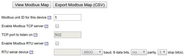
Check the box for "Enable Modbus" for the appropriate service (Modbus TCP uses Ethernet, Modbus RTU uses the eGauge USB485 serial converter).
For Modbus TCP, choose the port to listen on (default: 502).
For Modbus RTU, click inside the serial device box and detected adapters will be listed to choose from as shown below. Choose the appropriate baud rate, parity and stop bits to match the Modbus master.

Modbus Register Map
The exact Modbus map depends on the eGauge device configuration and is available on the Modbus settings screen. The map is available for viewing in the web browser or for download as a comma-separated value (CSV) file which can then be imported into any spreadsheet program.
|
Address range |
Description |
|
Timestamps |
|
|
30000 -- 30003 |
local timestamp (for use when reading from addresses <35000) |
|
30004 -- 30007 |
THD timestamp indicates when data was acquired that is used by FFTarg(), FFTarg2(), FFTmag(), and THD() functions |
|
30008 -- 30009 |
register timestamp (for use when reading from addresses ≥35000) |
|
Local data (channel checker) |
|
|
30500 -- 30999 |
Line voltages (RMS) |
|
31000 -- 31499 |
Line voltages (DC/mean) |
|
31500 -- 31999 |
Line frequencies |
|
32000 -- 32499 |
Sensor values (normal/RMS) |
|
32500 -- 32999 |
Sensor values (mean/DC) |
|
33000 -- 33949 |
Sensor frequencies |
|
Register Data [v4.0 and greater] |
|
|
34000 -- 34999 |
Reduced precision cumulative physical register values (float) |
| 35000 -- 35999
|
Cumulative virtual register values (signed 64-bit integers) |
| 36000 -- 36999 |
Change of virtual register value (float) |
| 37000 -- 37999 | Reduced precision cumulative virtual register values (float) |
| 38000 -- 38999 | Cumulative physical register values (signed 64-bit integers) |
| 39000 -- 39999 | Change of physical register value (float) |
|
Register Data [PRIOR to firmware v4.0, now deprecated] |
|
|---|---|
|
35000 -- 35999 |
Cumulative register values (signed 64-bit integers) [DEPRECATED] |
|
36000 -- 36999 |
Change of register value (float) [DEPRECATED] |
|
37000 -- 37999 |
Reduced precision cumulative register values (float) [DEPRECATED] |
In v4.0 or greater, the Modbus addresses are tied to the eGauge register IDs. They can be calculated as:
Physical float cumulative value = 34000+(ID*2)
Physical s64 cumulative value = 38000+(ID*4)
Physical float instant value = 39000+(ID*2)
Virtual registers are in the order they appear on the installation settings page, and are therefore liable to shift during deletions or additions.
The register ID can be found by hovering over the register delete button in the Installation Settings page:

An example Modbus map, which can be found in Settings -> Modbus Server, is displayed below:


The t16 type Modbus registers are variable-length UTF-8 strings and therefore multiple registers may need to be read until a UTF-8 null character is reached.
Example Modbus Transmissions:
Example Modbus TCP request and response for L1 RMS voltage:
Request: [00 01] [00 00] [00 06] [01] [04] [01 f4] [00 02]
[00 01] = Transaction identifier
[00 00] = Protocol identifier (always 00 00)
[00 06] = Bytes following (0x0006 = 6 bytes)
[01] = Unit ID
[04] = Function code (0x04 is read input registers)
[01 f4] = Starting register address (500)
[00 02] = Number of words to return (2 words for float value)
Response: [00 01] [00 00] [00 07] [01] [04] [04] [42 f6 2a 06]
[00 01] = Transaction identifier
[00 00] = Protocol identifier (always 00 00)
[00 07] = Bytes following (0x0007 = 7 bytes)
[01] = Unit ID
[04] = Function code (0x04 is read input registers)
[42 f6 2a 06] = Contents of register 500 and 501 respectively
0x42f62a06 decoded as big-endian (ABCD) float is roughly 123.08, so L1 voltage is 123.08Vrms
Example Modbus RTU request and response for L1 RMS voltage:
Request: [01] [04] [01 f4] [00 02] [31 c5]
[01] = Unit ID
[04] = Function code (0x04 is read input registers)
[01 f4] = Starting register address (500)
[31 c5] = CRC error check
Response: [01] [04] [04] [42 f6 2a 06] [90 ac]
[01] = Unit ID
[04] = Function code (0x04 is read input registers)
[04] = Data bytes to follow (not including CRC)
[42 f6 2a 06] = Contents of register 500 and 501 respectively
0x42f62a06 decoded as big-endian (ABCD) float is roughly 123.08, so L1 voltage is 123.08Vrms
Additional technical information
The maximum Modbus frame size is 255 bytes. This translates to (61) 32-bit registers or (30) 64-bit registers. Most DAS and Modbus systems will automatically split any requests to limit the response size to not exceed the upper limit. If requesting more registers than can be returned in a single frame, the response may be truncated or an exception may be returned.
Additional help is available by clicking the [?] buttons on the Modbus Server settings page.
All data is provided as Modbus input registers and therefore their Modbus addresses start at 30000. The raw frame sent does not include the prefixed '30', this indicates the function code used.
For each register recorded by eGauge, the register's current cumulative value and the amount by which it changed since the previous one-second interval can be read. The cumulative value is available with full resolution as a signed 64-bit value. For convenience, the same value is also available, at reduced resolution, as a 32-bit floating point number. The change-in-value is available only as a 32-bit floating point number. In addition to the register data, it is also possible to read locally measured data such as line-voltages, frequencies, and the value measured by each sensor-port.
The Modbus server guarantees that any data read with a single request is consistent. Timestamps are provided as a means to ensure consistency when data is read with multiple requests (e.g., to read multiple, discontiguous registers). This is accomplished by (i) reading the timestamp, (ii) performing the desired read requests, and (iii) reading the timestamp again. If the two timestamp values are the same, then reader can be certain that the data is consistent.
Sunspec Support
Sunspec is a communication standard used by many types of devices (including inverters). It is intended to ease configuration when working with hardware from different manufacturers by providing common addressing block for different device types and allowing devices to query for applicable address blocks. Essentially, Sunspec allows a Modbus master (such as the eGauge) the ability to read the list of available registers from a device, eliminating the need to create inline definitions manually.
It's fairly easy to configure a Sunspec remote device:
1. Create a new remote device entry.
2. Name the entry (names are arbitrary but should make sense to the user).
3. Select the appropriate protocol. "Serial" for Modbus RTU, and "Modbus TCP" for Modbus TCP.
4. Enter the device address. This is in the form "modbus://sunspec.<id>@<addr>" where <id> is replaced with the Modbus slave address of the remote device and <addr> is replaced with the address of the remote device.
4a. With Modbus RTU, the address will be a USB port (USB1 or USB2) along with serial settings in the form ": baud / databits parity stopbits". For example, @USB1:9600/8n1 would indicate USB port 1, 9600 baud, 8 data bits, no parity, 1 stop bit.
4b. With Modbus TCP, the address will simply be the IP address of the Sunspec device on the local network. For example, @192.168.1.25 would indicate the remote device is located at 192.168.1.25.
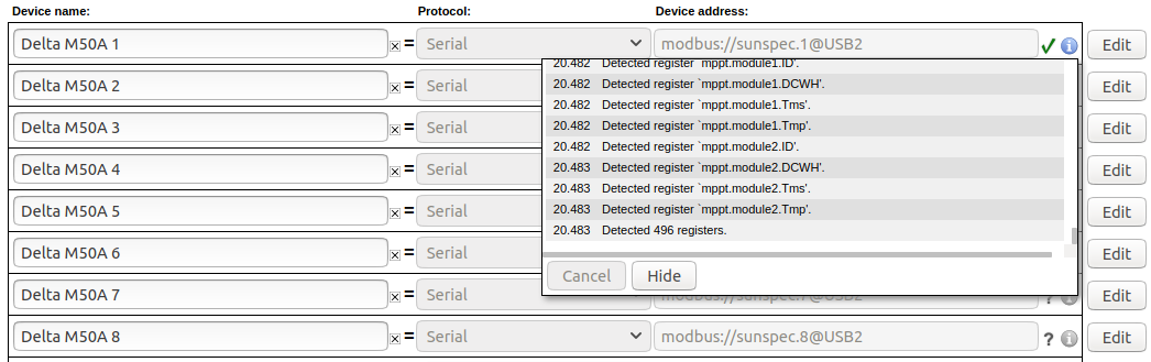
5. Click the grey "?" to the left of the device address. This will cause the eGauge to query the remote device for a full list of registers, and a green checkmark will appear if the query was successful. A red "X" will appear if the address is invalid or incorrectly entered. Click the blue info button to see detailed information on the state of the query (shown below).
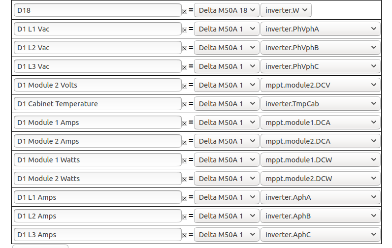
6. Once the register list has been retrieved, the eGauge needs to be configured to store registers of interest. To do this, create a new physical register, set the register type to the remote device name used in step 2, and then use the dropdown menu to select the remote register to record. The eGauge will only record the registers configured in this step, regardless of how many registers exist on the remote device.
7. Click the "Save" button at the bottom of the page to save these changes. The eGauge must be rebooted after adding new registers (this process typically takes about 30 seconds).
To add additional registers from a remote device, repeat steps 5 and 6.
Custom Modbus definitions (read from any Modbus device)
Overview
Current firmware allows the eGauge meter to record data from remote devices using Modbus RTU (using the USB485 USB-to-serial converter) and Modbus TCP (Ethernet).
If the remote device supports SunSpec over Modbus, there is not a need to create a Modbus Map. Instead, configure the remote device as a SunSpec device as described in this article.
Contents
Accessing the Modbus Map Editor
Accessing the Modbus Map Editor
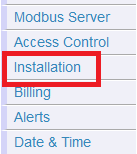
The Modbus Map Editor can be accessed through the Installation Settings screen by clicking the "Modbus Maps" button under the "Remote Devices" section:

A list of available Modbus maps will load. From here, maps can be created, edited, shared, or applied to the meter.
Creating a New Map
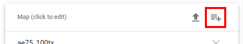
To create a new map, click or tap the icon in the top right corner of the page.
This will open a new page.
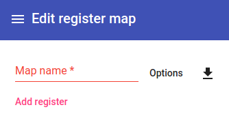
First, enter an appropriate map name. Typically, this should identify the hardware. Hardware model numbers are recommended. Click the "Save" button in the bottom right corner of the page to create an empty map with this name. The meter will load the list of available maps again, with the new (empty) map at the top. Click on this again to return to the empty map.
Adding Registers
To add registers, click the "Add Register" button. Enter the appropriate information for your register. "Scale" and "Offset" are optional values; all other fields must be filled. This information will be available in the documentation for the third party hardware - if it is not, it will be necessary to contact that hardware manufacturer directly. eGauge Systems cannot provide Modbus register maps for third party hardware.
As an example, the manufacturer's Modbus register map used to create the register below is available here: XY-MD02 manual. Note that Modbus register maps are not standardized, and it may require some effort to find the values required for eGauge configuration in a given map.
Below is an example register:
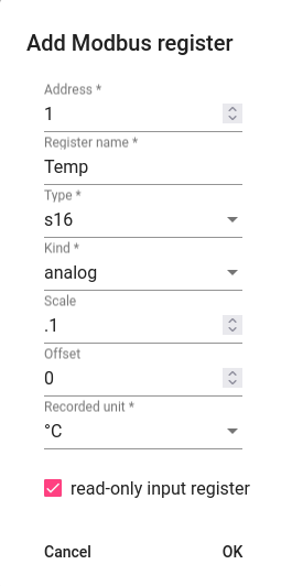
Address
Modbus register address, in decimal form. Note that Modbus documentation is not consistent, and it may be necessary to modify the address. For example, many addresses are listed with a preceding 3 or 4, but this number is usually dropped along with any preceding 0s. Thus, 30001 becomes 1, 40258 becomes 258, and so on. Some addresses may have a +/- 1 offset, so 301 might actually need to be entered as 300. Finally convert hex values (which usually start with 0x) to decimal values using a hexidecimal to decimal converter.
Register Name
The register name is an arbitrary value, but should reflect the item being measured for the sake of clarity. For example, "Temperature" implies a temperature measurement. "Ambient Temperature" might be a better fit for a device which records multiple temperature measurements.
Type
The data type of the register. If this setting is not correct the register data will not be read correctly, although it will usually read something. 32 and 64 bit data types read more than one Modbus register (a single Modbus register is 16 bits). In the absence of a defined data type, a register described by an address range (eg, 10-11, or 1000-1003) is likely a 32 or 64 bit register.
Kind
The kind of register. There are three options:
Analog - A simple numerical value. Most applications will use analog values.
Bitset - A numerical value representing a binary string. Typically, each 1 or 0 in this string would represent a state on the remote device. This selection is never averaged or allowed to accumulate excess, because it would change the fundamental value.
Enum - A numerical value representing a state on the remote device. This selection is never averaged or allowed to accumulate excess, because it would change the fundamental value.
Scale
Applies a scale factor to the raw value read from the Modbus device. This may be used to scale incoming values to better fit a certain data type. In the example above, the Temperature register at address 1 records temperature in .1 C increments, but the eGauge uses C as a unit. A raw value of 334 would therefore be displayed and recorded as 33.4 degrees Celsius with a .1 scale factor. If left blank, this is set to "1".
Offset
Applies a numerical offset to a raw value. This may be used for calibration purposes (eg, if a sensor is known to read 2 units too low, an offset of 2 would display the reading from that sensor as "raw_value + 2"). If left blank, this is set to "0".
Recorded Unit
Associates a supported unit with the value recorded from that register. This assigns a unit to the register in the eGauge user interface. For unsupported units, "record as integer" will record whole numbers and "record with 3 digits" will record fractional numbers to three digits (note that the incoming data may not actually be precise to three digits).
Read-only Input Register
The eGauge supports reading values from remote devices using either function code 3 (read holding registers) or function code 4 (read input registers). By default, function code 3 is used. However, some devices may only support function code 4 - in this case, selecting "read-only input register" will force the eGauge to use function code 4 for that register. Note that it is possible to use a mix of function codes on a single device.
Once a register has been added, click "OK" to save that register into the map. The register will be added to the map, and additional registers can be added by clicking the add icon in the top right corner of the page.
This example device has two registers, shown configured below:
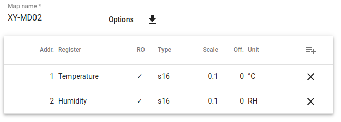
Make sure to click "Save" in the bottom right corner of the page once all registers are added. Navigating away from the page before clicking save will revert all changes (including newly added registers).
Adding Default Options
This section allows the user to specify various communication options on a per-device level. There are four options which can be set. Note that some of these options are mutually exclusive or not required depending on the device type. For example, a serial device (Modbus RTU) will not have a default TCP port.
Default Unit Number
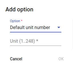
The default unit number is also referred to as "Modbus ID", "Modbus slave address", "Slave address", and so on. Each device on a single serial chain must have a unique unit number. Typically, hardware will ship with a default unit number, so if multiple devices from the same manufacturer are preset the unit number must be set to a unique value on each device.
The process for changing a device's unit number depends on the hardware - reach out to the hardware manufacturer for additional information or instructions.
Default Serial Port Parameters
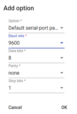
Only applies to Modbus RTU devices
Most Modbus RTU devices ship with a predefined set of serial parameters. These include baud rate, data bits, parity, and stop bits. These parameters must be identical across all devices on a single serial chain. If using multiple identical devices they should all be set to use the same values, but devices from different manufacturers may need to be set so they all use the same serial parameters.
The process for changing serial parameters depends on the hardware - reach out to the hardware manufacturer for additional information or instructions.
Default TCP Port
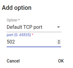
Only applies to Modbus TCP devices
Most Modbus TCP devices ship with a default TCP port of 502. However, in some cases this may not be true, or it may be desirable to use a different TCP port. TCP ports do not need to match across multiple Modbus TCP devices, even on the same network (each Modbus TCP device should have a unique IP address, so the port used is immaterial).
Base Address

The base address field can be used to apply a starting address for registers. This can be useful if a manufacturer's Modbus map has a +/-1 offset, or if the addresses all require a specific prefix (eg, 30000, 40000, 1000). The address queried by the eGauge will be (base address) + (configured address).
If in doubt, this setting can generally be ignored.
Sharing Modbus Maps
Modbus maps can be downloaded and shared as CSV files. There is no charge for this service. This can be used to copy a single map to multiple meters, or to share a map with other users. For best results, ensure that the source and destination meters are both on the same firmware version.
Always verify that maps downloaded from unknown sources are valid and complete. A misconfigured map can't cause damage to the eGauge, but it might not work correctly or may report incorrect values.
Downloading a Map
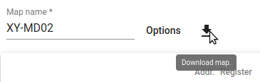
To download a Modbus map, select the desired map from the map list and click the "Download" button. A confirmation window will appear:
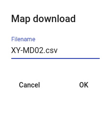
After clicking "OK", the map will be downloaded as a CSV file.
Although it is possible to edit the CSV file directly, this is not supported or recommended.
Uploading a Map
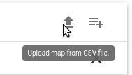
To upload a Modbus map, click the "Upload" button in the top right corner of the map list. A confirmation window will appear:
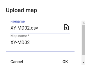
Click the "Filename" field to select the location of the saved map on your computer or device. Optionally, enter the desired map name. Click "OK" to upload the map.
An error message will appear at the bottom of the page if the map is invalid, corrupted, or incomplete.
Modbus maps can be shared freely as desired. eGauge Systems makes no guarantees as to the correctness or validity of these maps. When uploading a map, always verify that map configuration is correct and complete.
Using a Modbus Map
Once a Modbus map has been fully configured and saved, it can used in remote device addresses (under Settings -> Installation). Note that a map doesn't do anything until it's added as a remote device and at least one local register is created to store data based on that map.
The process for this varies based on whether the map applies to a Modbus RTU or Modbus TCP device. Make a note of the map name - it will be required to configure the eGauge.
Modbus RTU
Modbus RTU device addresses are prefixed with modbus:// and end with the address of either a USB port when using the USB-RS485 adapter (USB1 or USB2) or the MAC address of a Serial to Ethernet converter.
The protocol type "Serial" should be selected for all Modbus RTU devices.
In the example below, the map XY-MD02 is associated with a serial to USB adapter in USB port 1

Serial settings can also be added if default serial settings weren't specified in the map or if different serial settings need to be used. For example:

In the above example, the serial settings are:
| Baud | Data Bits | Parity | Stop Bits |
| 9600 | 8 | n (none) | 1 |
Finally, it's also possible to specify a different Modbus address/slave address/unit number. This will be necessary if a default value isn't specified or if multiple devices are on the same serial chain. To do this, add the address in the form .X after the map name, where X is the address. For example:

In the above example, an address of 55 is used instead of the default.
Modbus TCP
Modbus TCP devices have no prefix, and end with the IP address or MAC address of the Modbus device on the local network. Note that Modbus TCP devices must be on the same local network as the eGauge.
The Protocol type "Modbus TCP" should be selected for all Modbus TCP devices.
In the example below, the map XY-MD02 is associated with the address 192.168.1.25 (presumably the same network the eGauge is connected to):

A different Modbus address/slave address/unit number may also need to be specified. To do this, add the address in the form .X after the map name, where X is the address. For example:

In the above example, an address of 55 is used instead of the default.
Creating a Local Register
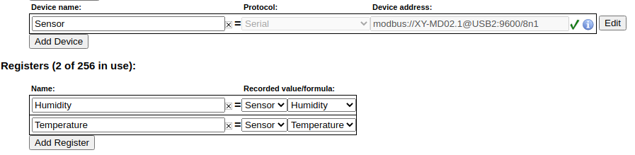
To create a local register and record data from a remote device, you must first validate the Modbus address. To do this, click the grey "?" to the left of the remote device address. A green check mark should appear. If a red "X" appears, it means the remote device is unreachable or the address or map is configured incorrectly.
Once the green check mark appears, registers can be added to the eGauge configuration to store data fetched from the Modbus device. In the example below, the eGauge is importing two registers ("Humidity" and "Temperature") from the remote device "Sensor":
After adding registers, make sure to save changes by clicking "Save" at the bottom of the page.
For an introduction to making configuration changes to the eGauge, see this article.
Creating, Sharing, and Using Modbus Maps
Overview
Current firmware allows the eGauge meter to record data from remote devices using Modbus RTU (using the USB485 USB-to-serial converter) and Modbus TCP (Ethernet).
If the remote device supports SunSpec over Modbus, there is not a need to create a Modbus Map. Instead, configure the remote device as a SunSpec device as described in this article.
Contents
Accessing the Modbus Map Editor
Accessing the Modbus Map Editor
The Modbus Map Editor can be accessed through the Installation Settings screen by clicking the "Modbus Maps" button under the "Remote Devices" section:
A list of available Modbus maps will load. From here, maps can be created, edited, shared, or applied to the meter.
Creating a New Map
To create a new map, click or tap the icon in the top right corner of the page.
This will open a new page.
First, enter an appropriate map name. Typically, this should identify the hardware. Hardware model numbers are recommended. Click the "Save" button in the bottom right corner of the page to create an empty map with this name. The meter will load the list of available maps again, with the new (empty) map at the top. Click on this again to return to the empty map.
Adding Registers
To add registers, click the "Add Register" button. Enter the appropriate information for your register. "Scale" and "Offset" are optional values; all other fields must be filled. This information will be available in the documentation for the third party hardware - if it is not, it will be necessary to contact that hardware manufacturer directly. eGauge Systems cannot provide Modbus register maps for third party hardware.
As an example, the manufacturer's Modbus register map used to create the register below is available here: XY-MD02 manual. Note that Modbus register maps are not standardized, and it may require some effort to find the values required for eGauge configuration in a given map.
Below is an example register:
Address
Modbus register address, in decimal form. Note that Modbus documentation is not consistent, and it may be necessary to modify the address. For example, many addresses are listed with a preceding 3 or 4, but this number is usually dropped along with any preceding 0s. Thus, 30001 becomes 1, 40258 becomes 258, and so on. Some addresses may have a +/- 1 offset, so 301 might actually need to be entered as 300. Finally convert hex values (which usually start with 0x) to decimal values using a hexidecimal to decimal converter.
Register Name
The register name is an arbitrary value, but should reflect the item being measured for the sake of clarity. For example, "Temperature" implies a temperature measurement. "Ambient Temperature" might be a better fit for a device which records multiple temperature measurements.
Type
The data type of the register. If this setting is not correct the register data will not be read correctly, although it will usually read something. 32 and 64 bit data types read more than one Modbus register (a single Modbus register is 16 bits). In the absence of a defined data type, a register described by an address range (eg, 10-11, or 1000-1003) is likely a 32 or 64 bit register.
Kind
The kind of register. There are three options:
Analog - A simple numerical value. Most applications will use analog values.
Bitset - A numerical value representing a binary string. Typically, each 1 or 0 in this string would represent a state on the remote device. This selection is never averaged or allowed to accumulate excess, because it would change the fundamental value.
Enum - A numerical value representing a state on the remote device. This selection is never averaged or allowed to accumulate excess, because it would change the fundamental value.
Scale
Applies a scale factor to the raw value read from the Modbus device. This may be used to scale incoming values to better fit a certain data type. In the example above, the Temperature register at address 1 records temperature in .1 C increments, but the eGauge uses C as a unit. A raw value of 334 would therefore be displayed and recorded as 33.4 degrees Celsius with a .1 scale factor. If left blank, this is set to "1".
Offset
Applies a numerical offset to a raw value. This may be used for calibration purposes (eg, if a sensor is known to read 2 units too low, an offset of 2 would display the reading from that sensor as "raw_value + 2"). If left blank, this is set to "0".
Recorded Unit
Associates a supported unit with the value recorded from that register. This assigns a unit to the register in the eGauge user interface. For unsupported units, "record as integer" will record whole numbers and "record with 3 digits" will record fractional numbers to three digits (note that the incoming data may not actually be precise to three digits).
Read-only Input Register
The eGauge supports reading values from remote devices using either function code 3 (read holding registers) or function code 4 (read input registers). By default, function code 3 is used. However, some devices may only support function code 4 - in this case, selecting "read-only input register" will force the eGauge to use function code 4 for that register. Note that it is possible to use a mix of function codes on a single device.
Once a register has been added, click "OK" to save that register into the map. The register will be added to the map, and additional registers can be added by clicking the add icon in the top right corner of the page.
This example device has two registers, shown configured below:
Make sure to click "Save" in the bottom right corner of the page once all registers are added. Navigating away from the page before clicking save will revert all changes (including newly added registers).
Adding Default Options
This section allows the user to specify various communication options on a per-device level. There are four options which can be set. Note that some of these options are mutually exclusive or not required depending on the device type. For example, a serial device (Modbus RTU) will not have a default TCP port.
Default Unit Number
The default unit number is also referred to as "Modbus ID", "Modbus slave address", "Slave address", and so on. Each device on a single serial chain must have a unique unit number. Typically, hardware will ship with a default unit number, so if multiple devices from the same manufacturer are preset the unit number must be set to a unique value on each device.
The process for changing a device's unit number depends on the hardware - reach out to the hardware manufacturer for additional information or instructions.
Default Serial Port Parameters
Only applies to Modbus RTU devices
Most Modbus RTU devices ship with a predefined set of serial parameters. These include baud rate, data bits, parity, and stop bits. These parameters must be identical across all devices on a single serial chain. If using multiple identical devices they should all be set to use the same values, but devices from different manufacturers may need to be set so they all use the same serial parameters.
The process for changing serial parameters depends on the hardware - reach out to the hardware manufacturer for additional information or instructions.
Default TCP Port
Only applies to Modbus TCP devices
Most Modbus TCP devices ship with a default TCP port of 502. However, in some cases this may not be true, or it may be desirable to use a different TCP port. TCP ports do not need to match across multiple Modbus TCP devices, even on the same network (each Modbus TCP device should have a unique IP address, so the port used is immaterial).
Base Address
The base address field can be used to apply a starting address for registers. This can be useful if a manufacturer's Modbus map has a +/-1 offset, or if the addresses all require a specific prefix (eg, 30000, 40000, 1000). The address queried by the eGauge will be (base address) + (configured address).
If in doubt, this setting can generally be ignored.
Sharing Modbus Maps
Modbus maps can be downloaded and shared as CSV files. There is no charge for this service. This can be used to copy a single map to multiple meters, or to share a map with other users. For best results, ensure that the source and destination meters are both on the same firmware version.
Always verify that maps downloaded from unknown sources are valid and complete. A misconfigured map can't cause damage to the eGauge, but it might not work correctly or may report incorrect values.
Downloading a Map
To download a Modbus map, select the desired map from the map list and click the "Download" button. A confirmation window will appear:
After clicking "OK", the map will be downloaded as a CSV file.
Although it is possible to edit the CSV file directly, this is not supported or recommended.
Uploading a Map
To upload a Modbus map, click the "Upload" button in the top right corner of the map list. A confirmation window will appear:
Click the "Filename" field to select the location of the saved map on your computer or device. Optionally, enter the desired map name. Click "OK" to upload the map.
An error message will appear at the bottom of the page if the map is invalid, corrupted, or incomplete.
Modbus maps can be shared freely as desired. eGauge Systems makes no guarantees as to the correctness or validity of these maps. When uploading a map, always verify that map configuration is correct and complete.
Using a Modbus Map
Once a Modbus map has been fully configured and saved, it can used in remote device addresses (under Settings -> Installation). Note that a map doesn't do anything until it's added as a remote device and at least one local register is created to store data based on that map.
The process for this varies based on whether the map applies to a Modbus RTU or Modbus TCP device. Make a note of the map name - it will be required to configure the eGauge.
Modbus RTU
Modbus RTU device addresses are prefixed with modbus:// and end with the address of either a USB port when using the USB-RS485 adapter (USB1 or USB2) or the MAC address of a Serial to Ethernet converter.
The protocol type "Serial" should be selected for all Modbus RTU devices.
In the example below, the map XY-MD02 is associated with a serial to USB adapter in USB port 1
Serial settings can also be added if default serial settings weren't specified in the map or if different serial settings need to be used. For example:
In the above example, the serial settings are:
| Baud | Data Bits | Parity | Stop Bits |
| 9600 | 8 | n (none) | 1 |
Finally, it's also possible to specify a different Modbus address/slave address/unit number. This will be necessary if a default value isn't specified or if multiple devices are on the same serial chain. To do this, add the address in the form .X after the map name, where X is the address. For example:
In the above example, an address of 55 is used instead of the default.
Modbus TCP
Modbus TCP devices have no prefix, and end with the IP address or MAC address of the Modbus device on the local network. Note that Modbus TCP devices must be on the same local network as the eGauge.
The Protocol type "Modbus TCP" should be selected for all Modbus TCP devices.
In the example below, the map XY-MD02 is associated with the address 192.168.1.25 (presumably the same network the eGauge is connected to):
A different Modbus address/slave address/unit number may also need to be specified. To do this, add the address in the form .X after the map name, where X is the address. For example:
In the above example, an address of 55 is used instead of the default.
Creating a Local Register
To create a local register and record data from a remote device, you must first validate the Modbus address. To do this, click the grey "?" to the left of the remote device address. A green check mark should appear. If a red "X" appears, it means the remote device is unreachable or the address or map is configured incorrectly.
Once the green check mark appears, registers can be added to the eGauge configuration to store data fetched from the Modbus device. In the example below, the eGauge is importing two registers ("Humidity" and "Temperature") from the remote device "Sensor":
After adding registers, make sure to save changes by clicking "Save" at the bottom of the page.
For an introduction to making configuration changes to the eGauge, see this article.