eGauge Installation
Covers topics related to the physical aspects of eGauge installation.
- eGauge Installation Examples
- Submetering
- Standard split-phase backfed
- Direct-feed Solar
- Three phase 120/208 or 277/480 Wye w/ single-phase inverter
- Monitoring 480V and 600V delta systems
- 120V or 208V Three-Phase Delta
- Three-phase High-leg delta
- Monitoring multiple services with one eGauge meter
- Subpanels
- Monitoring 347/600V Services
- Appliances
- 3-Phase Inverter
- Grouping Loads by Type
- Three-phase 120/208 or 277/480 Wye
- Panel phasing and eGauge installation
- Extending the length of the CT leads
- Protecting the eGauge with inline fuses
- Connecting directly to the eGauge
- Three-Phase installation tutorial
- Surges and overvoltage
- Monitoring High Voltage DC Loads
- Sensor Hub and Sensors
eGauge Installation Examples
Wiring diagrams and basic configuration examples for installing the eGauge on different types of electrical systems.
Submetering
The EG4xxx series meters are capable of monitoring up to 7 single-phase units (EG4015) or 15 single-phase units (EG4030) with a single meter. Single-phase units require 2 CTs each, one for each phase.
Please visit Getting Started for an overview of the physical installation and configuration process.
Example Wiring Diagram
Below is an example diagram of an EG4015 measuring 7 single-phase units on a distribution panel.
Ensure the meter's L1, L2, and L3 breakers are the same phases as the panels L1, L2, and L3 phases, or a phase-mixup will occur and recorded data will be incorrect. See this article for more information on phase checking.
The meter in the diagram shown below does not reflect the physical layout or dimensions of the eGauge meter.
Panel layout and installation will vary. The meter must be configured in software to match the physical installation before any data will be recorded.
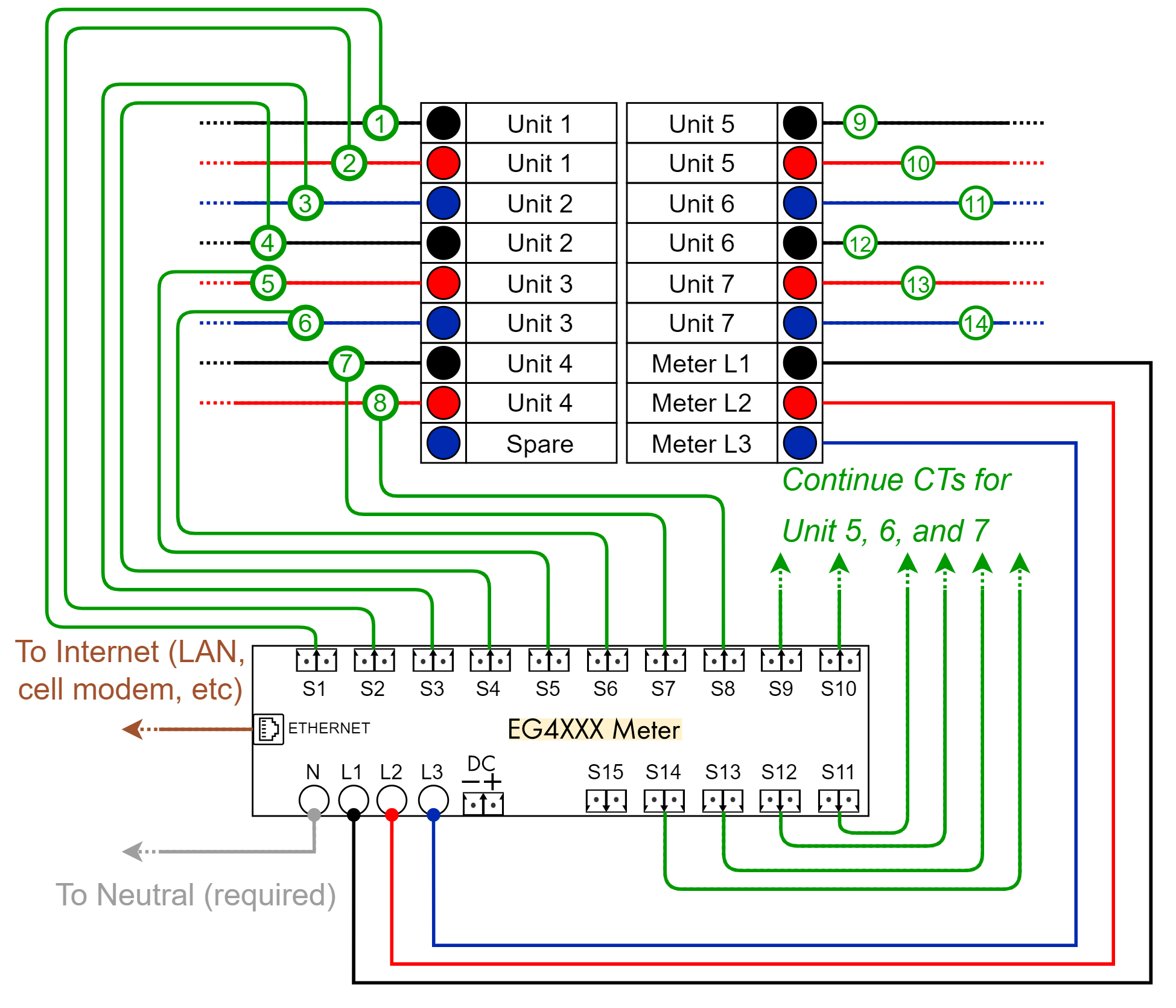
A diagram showing the CT connections for the last 3 units from above may be found here.
Example Configuration
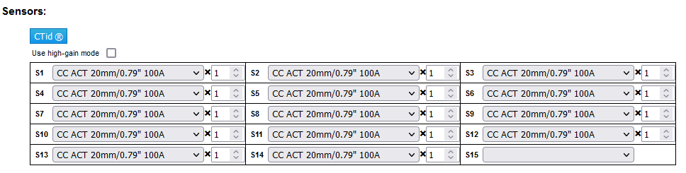
Sensors (CTs)
In most submetering installations the same model CT will be used on all breakers. In this example, all CTs are set as 100A 20mm AccuCTs. If using CTid CTs, please click the blue CTid button to configure CTid sensors.
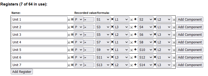
Registers
Registers define the data points the Gauge meter records. Each power calculation consists of a sensor input (S1, S2, S3...) that has the CT, and the voltage phase it is on (L1, L2, L3). Since each single-phase unit uses 2 CTs, there are 2 power calculations in each register added together to define the total usage of that unit.
Note, while the phasing pattern for units is typically staggered as L1 and L2, then L3 and L1, then L2 and L3, and so on, in the above example this changes with Unit 5 because the breakers for Unit 5, 6, and 7 begin on the right-hand side of the panel.
Standard split-phase backfed
Basic installation measuring power coming from a power utility (grid) and from a single-phase solar-system inverter
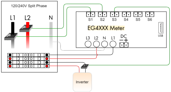
Registers:
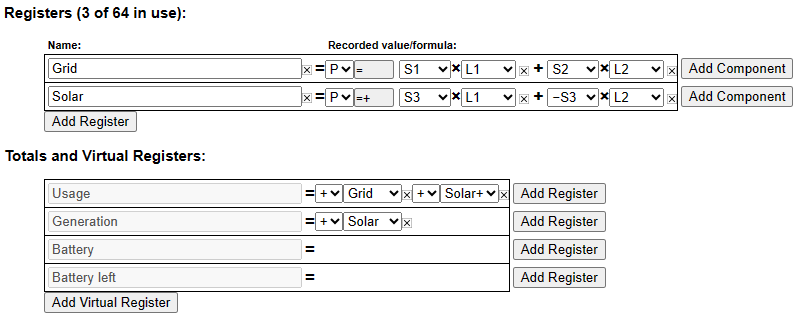
Notes:
- With a single-phase inverter, the current flowing at any given instant on leg L2 is the negative of the current flowing on leg L1. Hence, rather than using 2 CTs on the inverter, simply multiply the negated value of CT3 with L2 to calculate the power on that leg.
- The totaling rules indicate that total usage (consumption) is calculated as the sum of the power reported for register Grid and, the positive-only register Solar+. If the power reported for Solar is negative (indicating that the inverter is consuming power, e.g., during the night), then total usage is simply equal to the power reported for register Grid. It would be (slightly) wrong to define the Usage totaling rule as Grid + Solar because in this case, the inverter’s consumption would be canceled out of the usage, giving a lower than real consumption figure.
Direct-feed Solar
Same as Standard Split-Phase installation, except that the inverter feeds directly into the power utility’s grid. That is, the Solar CT is closer to the utility than the Grid CTs. This situation often arises when solar power is delivered via a line-side tap.
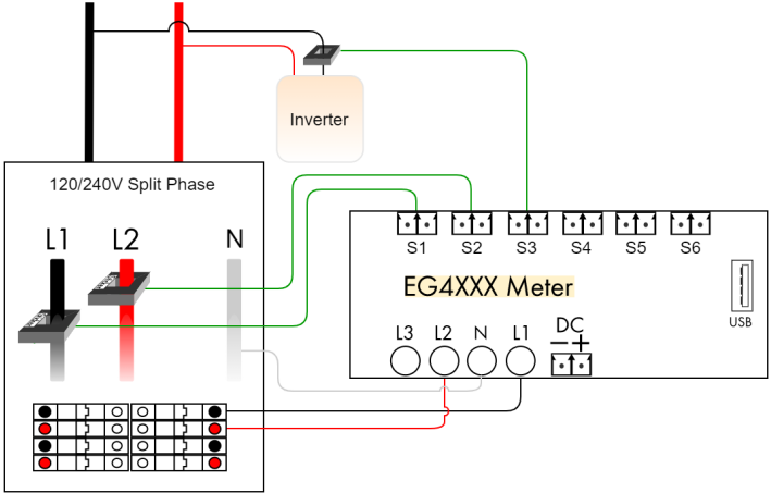
Registers:
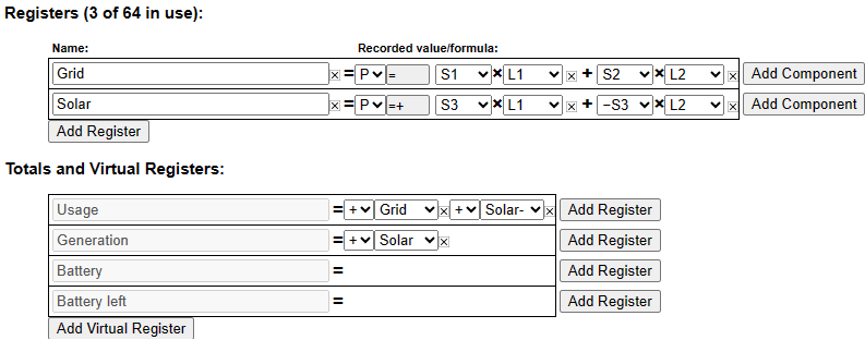
Notes:
- The only difference compared to the standard installation is that Solar+ was replaced by Solar- in the totaling rule for Usage. This is because the Grid CTs already capture total consumption, including any power coming from the solar system. The only exception is that when the inverter is consuming power (e.g., at night), that consumption is not captured by the Grid CTs. Adding Solar- corrects that because it will be equal to the amount of power consumed by the inverter, or zero when the inverter is producing power.
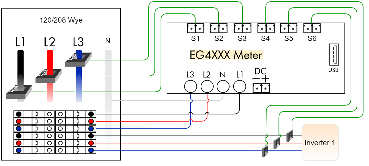
Three phase 120/208 or 277/480 Wye w/ single-phase inverter
Standard three-phase installation measuring power coming from a power utility (grid) and from a single-phase solar-system inverter. The color coding shows 120/208V, but applies to 277/480V as well. This diagram is for a Wye system with a neutral. Refer to delta diagrams for systems without neutral.
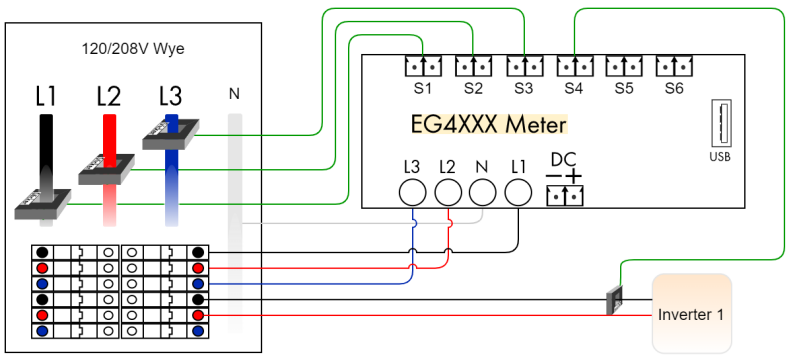
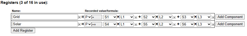
Registers:
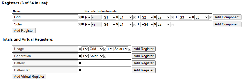
Notes:
- Three-phase installations are set up the same as split-phase systems, except that a third voltage-tap (L3) and a third Grid CT is required to measure power flow on phase 3.
- With multiple inverters, add one Solar CT per inverter and define a separate register for each inverter (e.g., Solar 1 and Solar 2). Adjust the register definition according to the CT that is measuring the current and the phases that the inverter feeds onto. For example, CT5 measuring current onto L2 and also feeding onto L3: Solar 2 = S5L2 + -S5L3.
- If there are more than three single-phase inverters, it is more economical to measure the total solar output with one CT per phase.
Monitoring 480V and 600V delta systems
- Never attempt to connect the eGauge directly to a 480V delta or 600V delta service using the "Lx" and "N" terminals.
- Connecting an eGauge meter directly to a 480V delta or 600V delta service will destroy the meter. This is not covered under warranty.
- The eGauge requires a connection to the "N" terminal, failing to connect a proper "N" can result in device damage.
The eGauge is capable of directly measuring voltages up to 277V L-N (480V L-L). In the case of a delta system with no neutral, the maximum phase-to-phase voltage is 277V as the "N" terminal of the meter has one of the line voltages connected.
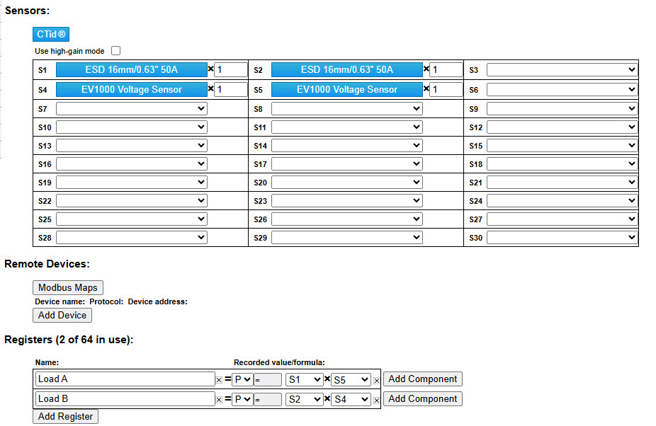
A 480V or 600V delta without a neutral may be monitored by the eGauge using EV1000 High Voltage Sensors.
The below diagram shows a 480V delta system. 600V delta systems may be measured in an identical manner.
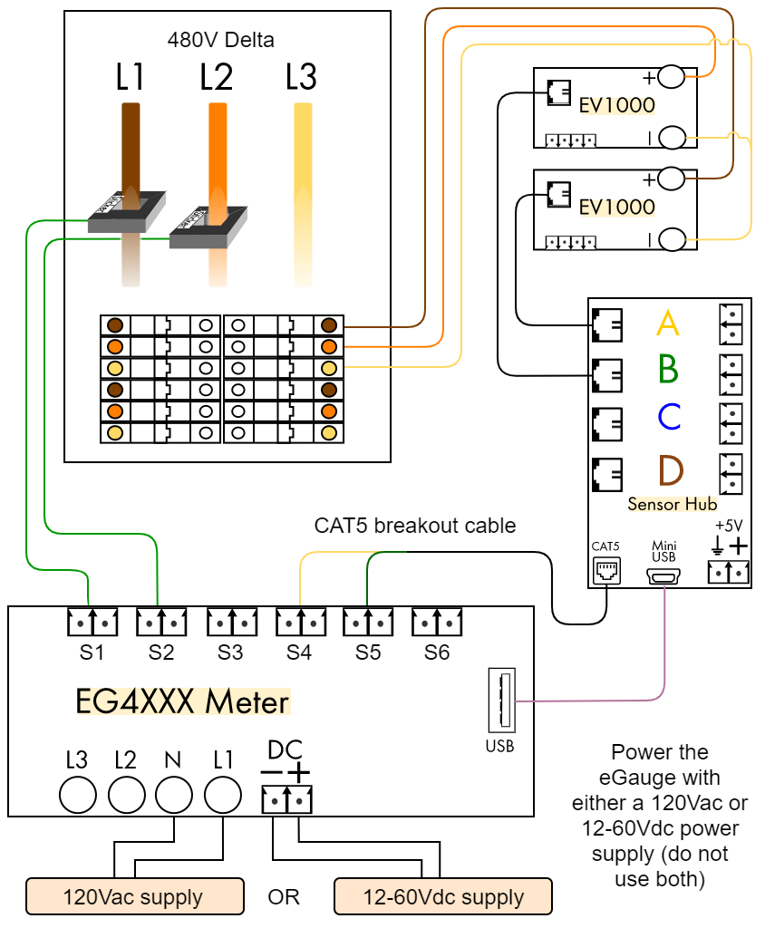
EV1000 high voltage sensors are CTid-compatible. See this article for instructions on configuring CTid-compatible sensors.
The register configuration for the example shown above is simply S1xS4 + S2xS5. Note that your configuration may differ depending on which ports are used.

Proper CT/phase pairing is required for accurate readings.
Notes:
The eGauge is a Blondel Compliant meter and will measure accurately the total load of a three-wire three-phase service using two CTs when correctly installed as outlined in this document.
This method of eGauge installation employs the Two-Wattmeter Method of power measurement which is based on Blondel's Theorem. Blondel's Theorem essentially states that you need one less CT than the number of current carrying conductors in your service to accurately meter the total load of the service. Further research on these topics, if needed is left to the reader.
When completing an installation of this type it's particularly important to adhere to the wiring diagram included in this document. CT orientation must be consistent and phase verification should always be performed to ensure that there is no phase mismatch between CTs and their respective Line voltages.
120V or 208V Three-Phase Delta
Three-phase delta installation measuring power coming from a power utility (grid). The color diagram below shows a 208V delta, but this also applies to a 120V delta or 240V delta.
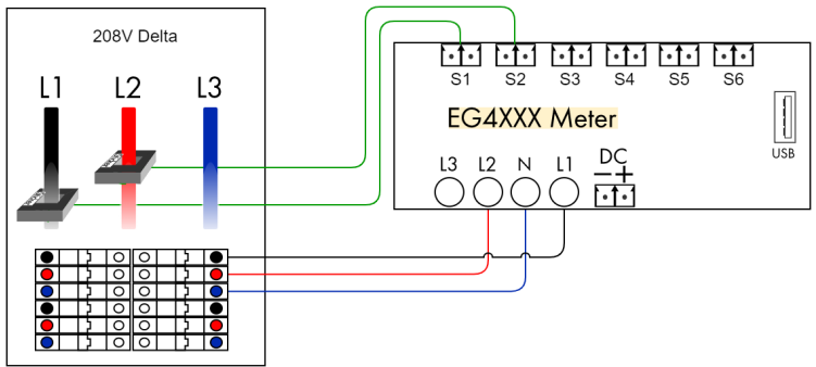
Registers:
Notes:
- CAUTION: Since there is no neutral and none of the phases may be grounded, all conductive/metallic parts, including CT-plug screws and CT wiring should be considered live and hazardous!
- If one of the phases is grounded, wire that phase to the Neutral (N) pin on the eGauge.
- The eGauge inputs can measure up to 277V L-N terminal. A 600V delta must be measured the same way as a 480V Delta.
-
The eGauge is a Blondel Compliant meter and will measure accurately the total load of a three-wire three-phase service using two CTs when correctly installed as outlined in this document.
This method of eGauge installation employs the Two-Wattmeter Method of power measurement which is based on Blondel's Theorem. Blondel's Theorem essentially states that you need one less CT than the number of current carrying conductors in your service to accurately meter the total load of the service. Further research on these topics, if needed is left to the reader.
When completing an installation of this type it's particularly important to adhere to the wiring diagram included in this document. CT orientation must be consistent and phase verification should always be performed to ensure that there is no phase mismatch between CTs and their respective Line voltages.
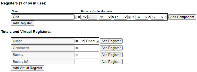
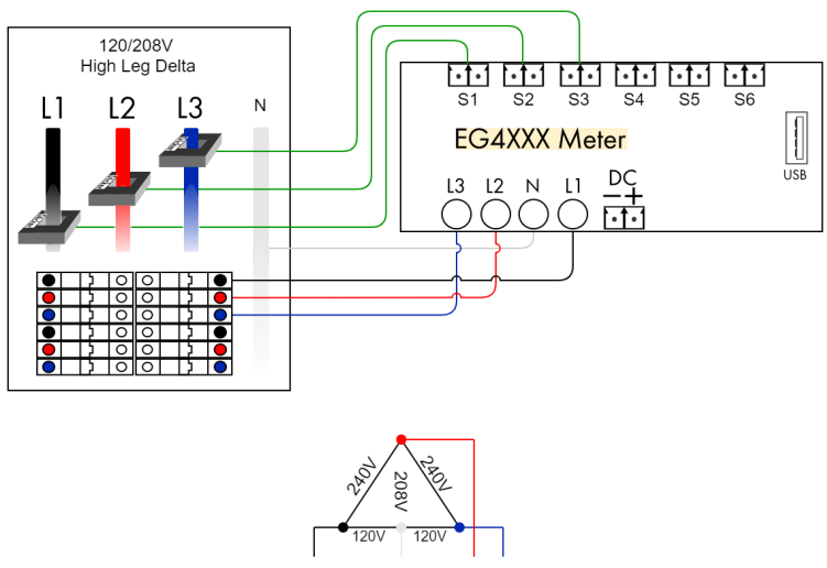
Three-phase High-leg delta
Three-phase high-leg delta installation measuring power coming from a power utility (grid).
Registers:
Notes:
- Wiring and configuration is identical to a standard three-phase site. The only difference is in the voltages measured on L1, L2, and L3: – L1 and L3 are 120Vac to neutral. – L2 is 208Vac to neutral.
- It does not matter whether the high-leg is wired to L1, L2, or L3, as long as all three phases are measured.
Monitoring multiple services with one eGauge meter
Overview
It's common to find sites with large stepdown transformers (e.g. to convert a 277/480V service to 120/208V for lighting or receptacle loads). To measure any AC load, the eGauge requires a combination of voltage references (Lx voltage terminals) and amperage references (CTs). It's not possible to measure loads on both the primary and secondary side of a transformer by simply scaling the voltage reference from either the primary or secondary side, because large transformers typically introduce an unknown and dynamic (varying in a non-linear relationship based on load profile) degree of phase shift between the primary and secondary side of the transformer. Until recently, the only option to accurately measure power in this scenario was to either use multiple eGauge meters (one with voltage references tapped on the secondary side of the transformer and one with voltage references tapped on the primary side of the transformer).
Using the ESH044 Sensor Hub and at least one EV1000 High Voltage Sensor (the number required will depend on the service type), it is possible to obtain voltage references from multiple services simultaneously. Note that each EV1000 sensor uses a port on the eGauge, so there are still limitations (any combination of CTs and EV1000 sensors, up to 15 or 30 depending on the eGauge meter model). An ESH044 Sensor Hub must be used - one sensor hub can support any combination of EV1000 sensors and CTs (up to four total devices per hub).
This guide only applies to EG4xxx meters. Older EG30xx and eGauge2 meters do not support the EV1000.
Installation Considerations
Typically, there are a few general rules to follow when monitoring multiple services:
1. The service with the lowest voltage should be connected directly to the eGauge, and the higher voltage service(s) should be monitored with the EV1000s. The eGauge can support a phase to neutral voltage of 277Vrms, while the EV1000 can support a voltage of up to 707Vac/1000Vdc, meaning the EV1000 is much more flexible than the meter itself.
2. Sensor Hubs must be powered. Up to 2 hubs can be powered directly from the eGauge via the USB ports on the meter. For installations where more hubs are required or the USB ports are in use (e.g., for Modbus RTU communication) the hubs can be powered directly from a generic 5Vdc power supply or a USB hub may be used.
3. All hardware must be installed in a suitably rated enclosure. eGauge Systems offers several powered enclosure kits which are suitable for this purpose. Most kits feature DIN rails (for mounting the eGauge meter and EV1000s securely) along with a powered receptacle and optional stepdown transformer (which can be used to power the 5Vdc supply for the sensor hubs and/or other supporting hardware).
Examples
The following are general examples which may be useful for planning a specific installation. Note that these examples may omit certain details (for example, not all ports are shown on the eGauge meter). These are intended to serve as guidelines only - always consult local code requirements when planning an installation.
Hardware appearance in the following diagrams may not reflect the actual size or layout of actual hardware. Refer to the product pages for actual measurements.
Configuration examples are correct for the diagram shown. Note that it is essential to associate CTs with the correct phase, and failure to do so will result in incorrect readings. Correct phasing can only be guaranteed using a multimeter to verify phasing.
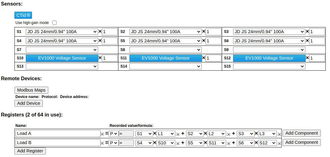
277/480V Wye and 120/208V Wye
In the following example, the eGauge is monitoring two loads - one on a 120/208V service, and one on a 277/480V service. Note that the neutral to loads A and B are not shown.
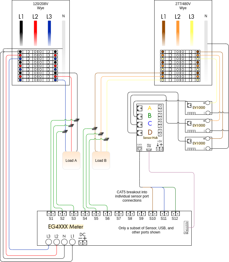
The meter configuration would be set as follows (note that the CT selection is filler - use the correct CTs for the actual installation):
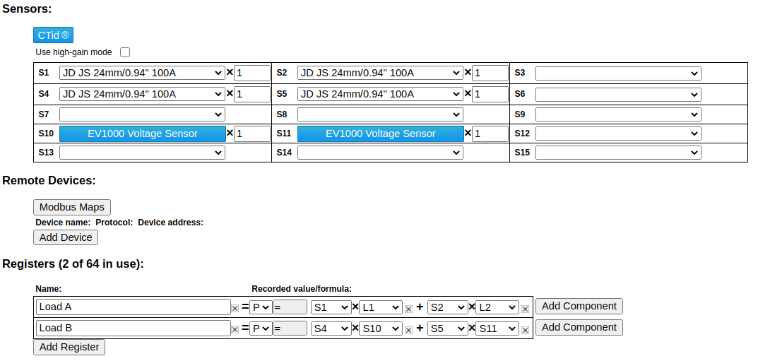
480V Delta and 208V Delta
In the following example, the eGauge is monitoring two loads - one on a 208V Delta service, and one on a 480V Delta service. Since no neutral is present, one phase on each service is effectively treated as a neutral - for the 208V service, C phase is connected to the N terminal, and for the 480V service, C phase is connected to the negative (-) terminals on the EV1000s.
In this configuration, only two CTs are required - one on each phase which is not connected to the N or (-) terminal.
480V delta services cannot be connected directly to the eGauge! Doing so will damage or destroy the meter. EV1000 sensors or stepdown transformers must be used to monitor a 480V delta service.

The meter configuration would be set as follows (note that the CT selection is filler - use the correct CTs for the actual installation). Again, for delta services only two CTs per three phase load are required:
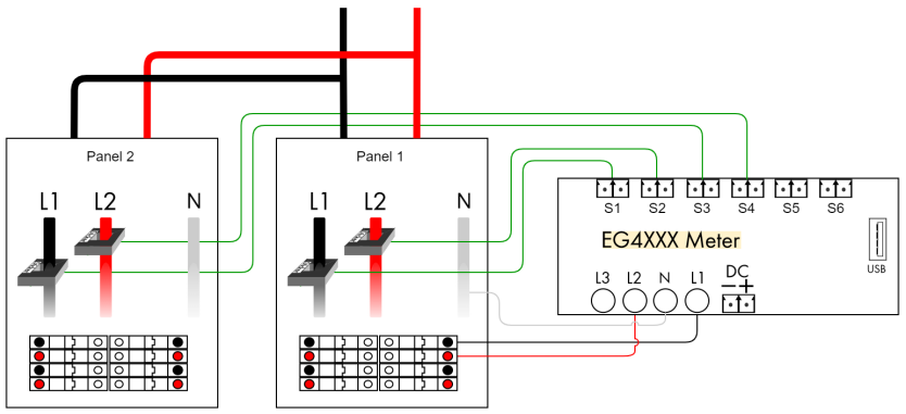
Subpanels
This example illustrates how to measure subpanels.
Registers:
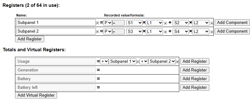
Notes:
- It does not matter which subpanel the meter obtains voltage from, but care must be taken to identify correct phasing. It is possible for phases to be reversed or inconsistent between panels.
Monitoring 347/600V Services
Overview
The 347/600Vac wye service (347V phase to neutral, 600V phase to phase) is rarely seen in the USA, although it's quite common in Canada. As the eGauge is only rated for 277Vac from phase to neutral (480V phase to phase), it traditionally could not be used to monitor such a service. However, with the introduction of the EV1000 High Voltage sensor, it's now possible to monitor these services directly, instead of using large and potentially inaccurate stepdown transformers.
To monitor a 347/600Vac service, the user will need one ESH044 Sensor Hub and three EV1000 High Voltage Sensors. An additional power supply is also required to power the eGauge (our standard 120Vac/12Vdc power supply can be used for this purpose if the barrel jack is removed).
This guide only applies to EG4xxx meters. Older EG30xx and eGauge2 meters do not support the EV1000.
Installation Considerations
1. All hardware must be installed in a suitably rated enclosure. eGauge Systems offers several powered enclosure kits which are suitable for this purpose. Most kits feature DIN rails (for mounting the eGauge meter and EV1000s securely) along with a powered receptacle and optional stepdown transformer (which can be used to power the 5Vdc supply for the sensor hubs and/or other supporting hardware).
2. Sensor Hubs must be powered. Up to 2 hubs can be powered directly from the eGauge via the USB ports on the meter. For installations where more hubs are required or the USB ports are in use (e.g., for Modbus RTU communication) the hubs can be powered directly from a generic 5Vdc power supply.
3. The eGauge must have a separate power source in this configuration. This can either be an AC power supply connected to the L1 and N terminals providing 120Vac - 277Vac or a DC power supply connected to the Ldc terminal providing 12-60Vdc. Note that correct polarity is required when using a DC power supply.
Examples
The following are general examples which may be useful for planning a specific installation. Note that these examples may omit certain details (for example, not all ports are shown on the eGauge meter). These are intended to serve as guidelines only - always consult local code requirements when planning an installation.
Hardware appearance in the following diagrams may not reflect the actual size or layout of actual hardware. Refer to the product pages for actual measurements.
Configuration examples are correct for the diagram shown. Note that it is essential to associate CTs with the correct phase, and failure to do so will result in incorrect readings. Correct phasing can only be guaranteed using a multimeter to verify phasing.
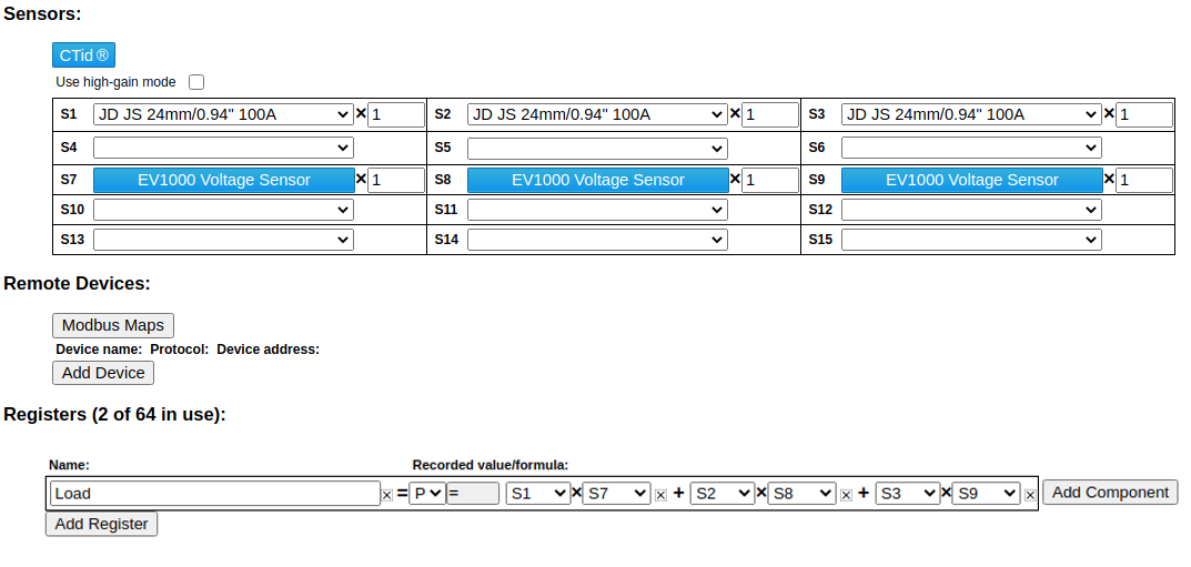
347/600V Wye
In the following example, the eGauge is monitoring a single load on a 347/600V panel. Note that the neutral connection to the load is not shown. The eGauge can be powered via AC or DC - both options are shown, but only one is required.
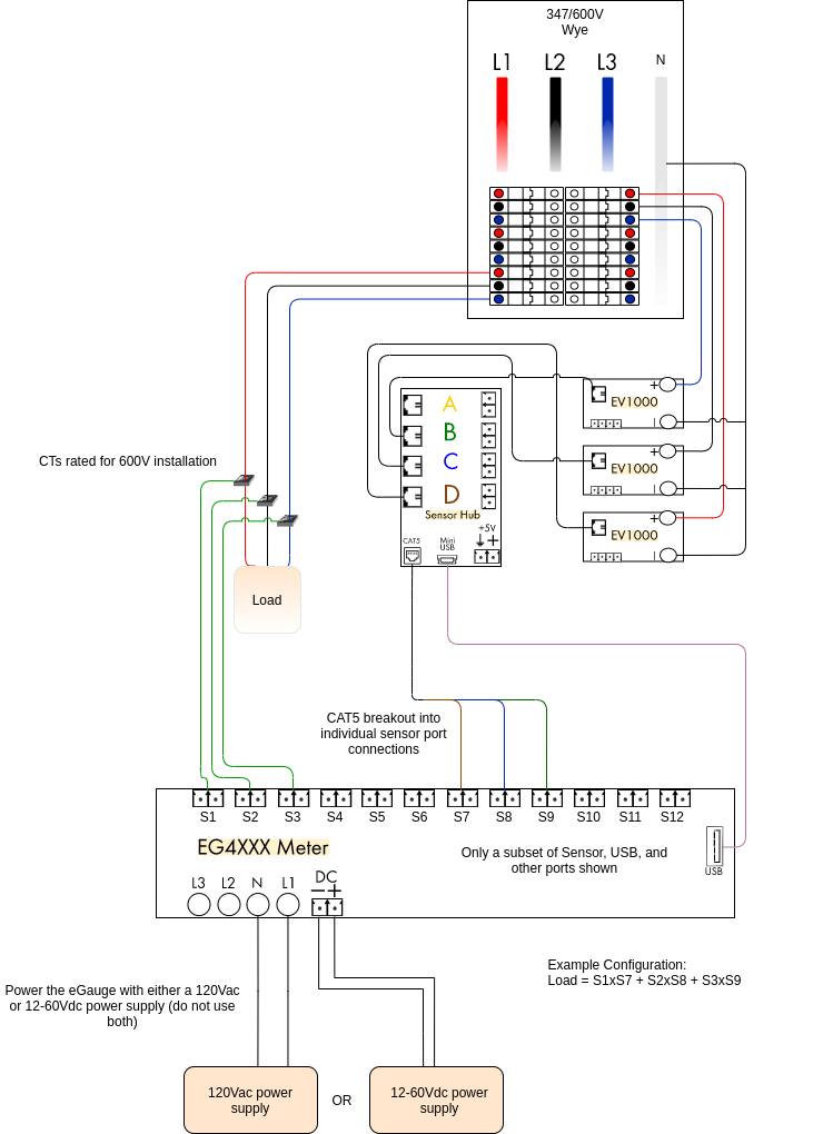
The meter configuration would be set as follows (note that the CT selection is filler - use the correct CTs for the actual installation):
Appliances
This example illustrates how to configure 120Vac (single pole) and 240Vac (two pole) appliances.
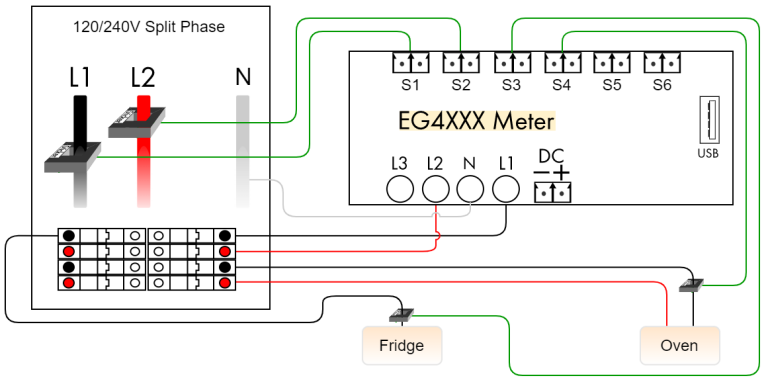
Registers:
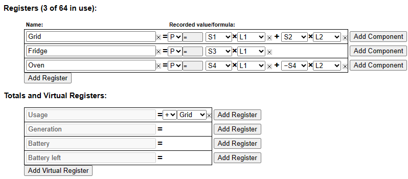
Notes:
- Registers defined for appliances do not appear in the totaling rules. Just defining the registers will make them appear in the appropriate places (e.g., in the legend of the dashboard graph).
- A single CT is sufficient both for 120Vac and pure 240Vac appliances. 240Vac appliances with asymmetric currents on the two legs (i.e., with a non-zero current on Neutral) require separate CTs per leg/phase.
3-Phase Inverter
Standard three-phase installation measuring power coming from a power utility (grid) and from a three phase solar-system inverter. The color coding shows 120/208V, but applies to 277/480V as well. This diagram is for a Wye system with a neutral. Refer to delta diagrams for systems without neutral.
Registers
Totals and Virtual Registers
Notes
- Three-phase installations are set up the same as split-phase systems, except that a third voltage-tap
(L3) and a third Grid CT is required to measure power flow on phase 3. - Three-phase inverters require a CT on each phase. Sometimes during low production they will not
output evenly on all 3 legs, and during standby they do not often draw the same amount of current on
each leg. Further, in standby, they may output power on certain legs and draw power on others, which
can lead to seeing erroneous overnight generation if a single CT is used. - If the solar is a line-side tap rather than back-fed, the Usage register should use Solar- rather than
Solar+. See configuration example 3.2, Direct-Feed Solar, for more information.
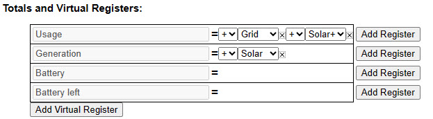
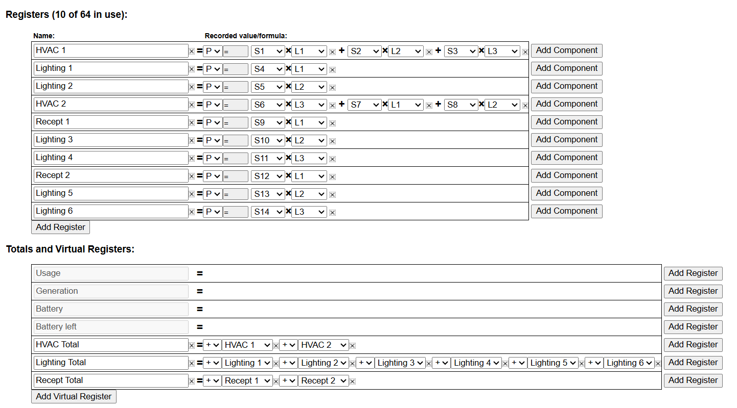
Grouping Loads by Type
In some installations there may be requirements to group loads in a panel by type. The eGauge meter allows for metering of individual loads which can then be totaled by type. Use this example for guidance.
Example wiring diagram
Registers
In this example, each panel sub load is configured individually as a physical register and totaling by type is done in the Totals and Virtual Registers section of the configuration settings. Take note of the phasing in the example registers below and how it relates to the wiring diagram above.
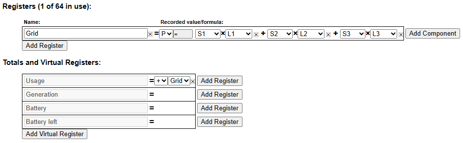
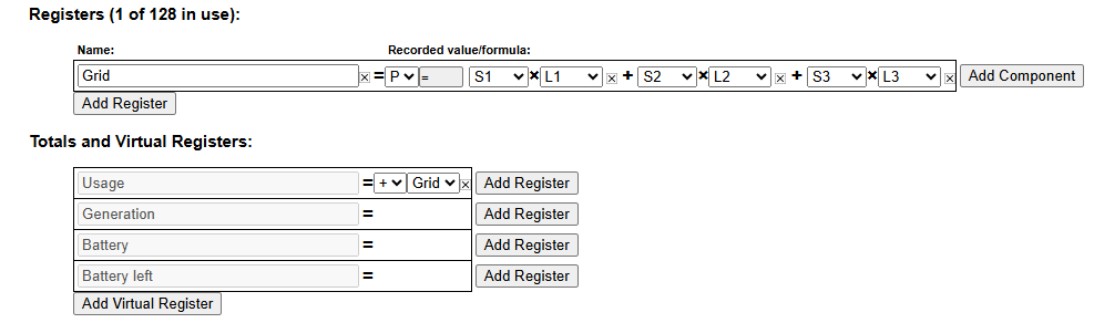
Three-phase 120/208 or 277/480 Wye
Standard three-phase installation measuring power coming from a power utility (grid). The color coding shows 120/208V but applies to 277/480V as well. This diagram is for a Wye system with a neutral. Refer to delta diagrams for systems without neutral.
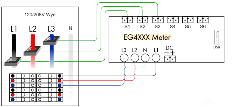
Registers
Notes
- Three-phase installations are set up the same as split-phase systems, except that a third voltage-tap (L3) and a third Grid CT is required to measure power flow on phase 3.
Panel phasing and eGauge installation
Correct phasing (associating a CT with the correct voltage reference) is a critical component of the eGauge installation. Ideally, phasing should be verified using a handheld multimeter to determine the phase of a conductor monitored by a given CT. Generally this is less of a concern for split phase services, but three phase services will encounter severe accuracy issues if phasing is incorrect.
eGauge technical support can offer assistance with determining correct phasing. However, correct phasing cannot be guaranteed in this manner. Correct phasing requires on-site verification, performed by a licensed electrician. eGauge does not suggest phase testing or opening electrical panels for any reason unless qualified to do so. Below is a description of panel phasing and a diagram, and for further reading a document with additional examples is below.
 PANEL PHASING GUIDE PANEL PHASING GUIDE |
The most common installation issue with retrofit energy metering is known as a phase mix-up, which will cause invalid power readings and often lower-than-expected power factor. In addition, the power readings may be the opposite of expected polarity (based on CT orientation).
In typical U.S. split-phase and three-phase panels, breakers alternate sequentially from top to bottom; three-phase services go A, B, C, A, B, C and so on. Breakers horizontally parallel are on the same phase; the top breakers on both sides are phase “A,” the next set of breakers are phase “B,” and so on. When monitoring incoming feeds of a 120/208-V panel, it’s generally expected for CT1 to measure phase A (black), CT2 to measure phase B (red) and CT3 to measure phase C (blue).
Often, the first unused or available breaker slot for a retrofit meter installation is not on the A phase, but instead may be on the B or C phase. For example, if the meter’s L1 voltage input is on a breaker using phase B, then L2 will land on C and L3 on A. Now there is an offset between the system’s true L1 and meter’s designated L1.
If the CTs are installed with CT1 on A (black), CT2 on B (red) and CT3 on C (blue), there is now a phase mix-up because CT1 is on the system’s A phase but the eGauge’s L3 phase. This issue is more likely to occur when the meter is not close to the CTs, so voltage connections cannot be directly traced between the eGauge and the panel.
The best method to confirm phasing is correct is to use a handheld voltmeter set for the AC voltage of the system. Place one probe on the L1 voltage terminal of the eGauge and the other probe to the conductor CT1 is around. A reading of 0 VAC indicates it is the same phase and CT1 is truly monitoring L1, while a reading of 208 V (or other phase-to-phase voltage) indicates they are different phases and CT1 is not on L1. This method can be used on any electrical service.
The eGauge Channel Checker tool and oscilloscope waveform viewer may be used to help identify phase mix-ups. If a phase mix-up is found, the software can be configured to apply the CT to the correct line without having to physically relocate the CTs.
We recommend this method be used in addition to other commissioning techniques on all retrofit energy meter installations to ensure correct readings and avoid problems that may require revisiting and inspecting the installation.

Extending the length of the CT leads
CTs may also be extended without splices or soldering using the eGauge Sensorhub as a CT extension kit.
Do not use wire nuts to connect CT extensions. Wire nuts will degrade and interfere with the low-voltage CT signals.
Split core CTs can be extended with twisted pair wire to cover longer distances. Twisted pair wiring is recommended, as it will reduce noise and interference. If you need to extend a CT wire farther than approximately 100 ft (30m), voltage drop must be taken into account and a larger gauge wire should be used.
Note that CT leads longer than approximately 100ft (30m) can cause a decrease in accuracy. This is especially true of CTs with high maximum amperage ratings which are reading extremely low amperages.
eGauge typically recommends 22 AWG to 18 AWG 600 V rated twisted pair wiring such as the type sold in our webstore. 600V rated CAT5 Ethernet cable can also be used, as it is generally easy to obtain and can be used to extend up to 4 CTs. However, any twisted pair wire with appropriate insulation and wire gauge can be used. Be certain to use twisted pair wire that is appropriately rated for the location and panels it will be run in. Shielded cabling may be helpful especially when running longer distances.
Connections should be made with solder and heat shrink tubing, butt connectors or inline lever connectors such as those sold with our CT Extension pack. Wire nuts must not be used to extend CT leads.
Please see the CT selection guide for full details regarding CTs.
Protecting the eGauge with inline fuses
As long as it is permitted by code, an inline fuse can be used to protect the eGauge. We suggest using a quick disconnect fuse block to allow the eGauge to be power cycled for troubleshooting if needed. A rating of 15A is suggested, but a larger or smaller fuse (between 5A and 50A) is also acceptable.
It is important to provide the end user with a reliable means of power cycling the eGauge. This is generally the first step in any sort of troubleshooting process. A fuse block which exposes the end user to line voltages is generally not adequate.
Connecting directly to the eGauge
Overview
The eGauge is most commonly accessed through the proxy server, using an address in the form http://DEVNAME.egaug.es, http://DEVNAME.d.egauge.net or https://DEVNAME.egauge.io. The eGauge may also be accessed via its IP address or hostname over the local network (commonly done to make configuration changes). However, both cases rely on a router or other networking hardware to establish a link between a computer and the eGauge.
In cases where it is not practical to connect the eGauge to a router, it is possible to connect to the eGauge directly using an Ethernet cable and a laptop or desktop computer with an Ethernet port. Connecting directly is often used for troubleshooting purposes, applying a device configuration prior to installation, or when leaving a device at a remote location where internet access isn't available. Tablets used in conjunction with USB to Ethernet adapters are not officially supported but may work.
Introduction to connecting directly
By default, the eGauge will attempt to obtain an IP address and associated information through a service called Dynamic Host Configuration Protocol (DHCP). If you cannot or do not wish to run this service on your LAN, or there is no LAN or network environment, the device will default to using IP address 192.168.1.88, so the device can be accessed at: http://192.168.1.88/.
The eGauge can be directly connected to a laptop or computer via an Ethernet to the built-in Ethernet port (EG4xxx and EG30xx), or to the HomePlug adapter (EG301x or older model eGauge2). This is often useful in environments with no local network, or where access to the network is restricted. In these scenarios, the eGauge can be configured and commissioned locally and directly; at a later time the eGauge can be retrieved and the data can be viewed and exported. On EG4xxx meters, data can also be exported to a USB thumb drive.
Please refer to the proper walkthrough for setting up your device to communicate with the eGauge, based on the operating system of the computer used to connect. These instructions assume that the eGauge is configured to use DHCP (not a static IP address).
Mac OS X (tested on Mountain Lion 10.7)
For advanced/experienced users:
Connect a computer to the same network as the eGauge, or directly to the HomePlug adapter or EG30xx/EG4xxx Ethernet port as stated above.
On the computer, set an IP address of 192.168.1.11, with a netmask of 255.255.255.0. Connect to the eGauge via device hostname, default IP of 192.168.1.88, or current static IP (if set). Note that a different IP address may need to be used on the computer if the eGauge's static IP address is not in the 192.168.1.xxx range.
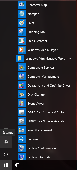
Microsoft Windows 10
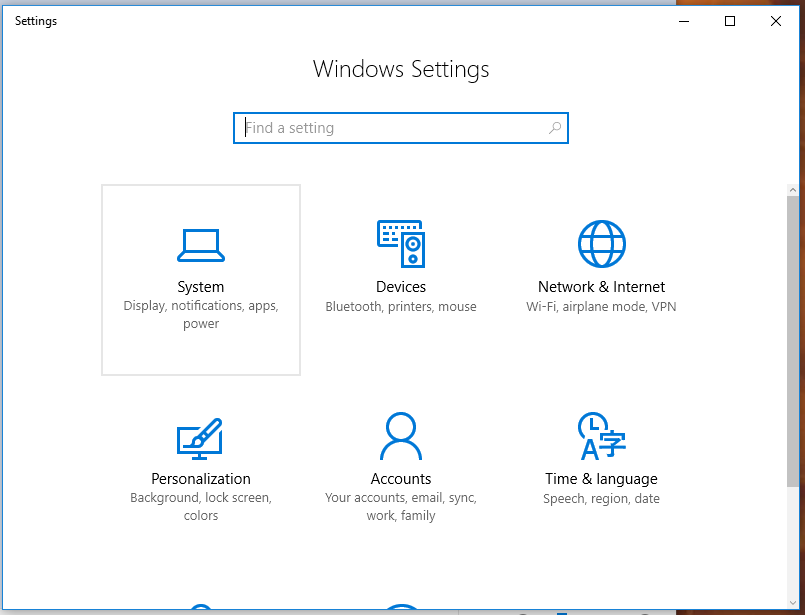
1. Open the Start menu and click the Settings icon (gear).
2. In the "Find a Setting" search bar at the top of the page, type "control panel" without quotes.
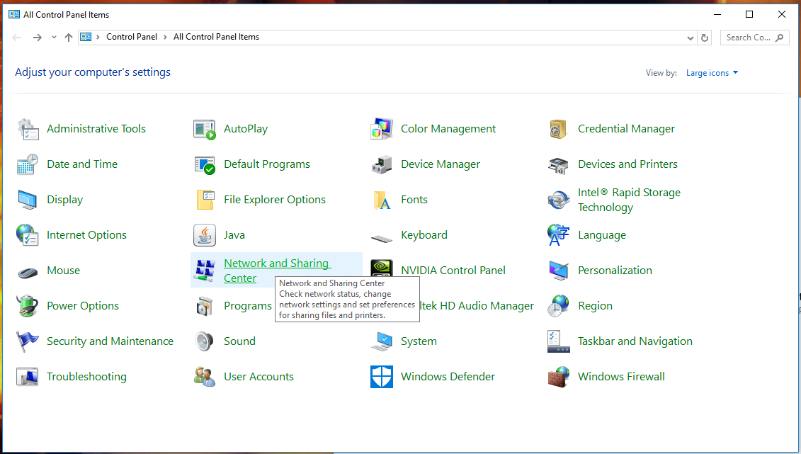
3. Once in the control panel, click "Network and Sharing Center".
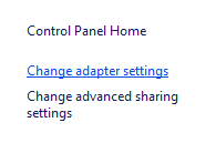
4. Select "Change Adapter Settings".
5. Disable any network connections you are not using to connect to the eGauge by right-clicking them and choosing Disable. This should be done for all wireless adapters when connected via Ethernet to the eGauge or HomePlug adapter.
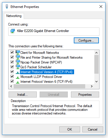
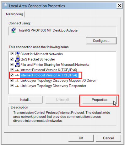
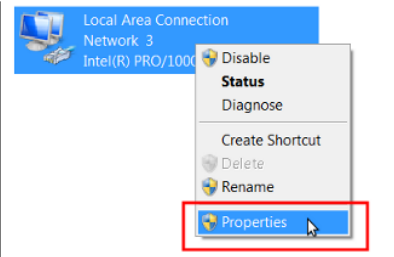
6. Right click the adapter you will be using to connect to the eGauge and choose Properties.

7. In the Properties window, click the item listed as Internet Protocol Version 4 (TCP/IPv4) and click the Properties button.
8. If Use the following IP address already contains values, write these down as they will be overwritten.

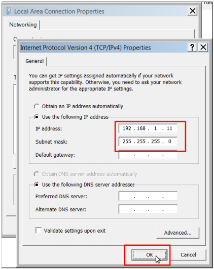
9. Click the radio button that says Use the following IP address and enter the following values:
IP address: 192.168.1.11
Subnet mask: 255.255.255.0
10. Click OK to save the changes and then click Close to close the properties window. To verify settings, right-click again on the adapter that was modified and choose Status and then Details. Look to see that IPv4 Address matches 192.168.1.11.
11. Access the eGauge at http://192.168.1.88. When done accessing the eGauge, revert any adapter’s properties that you have changed during this process.
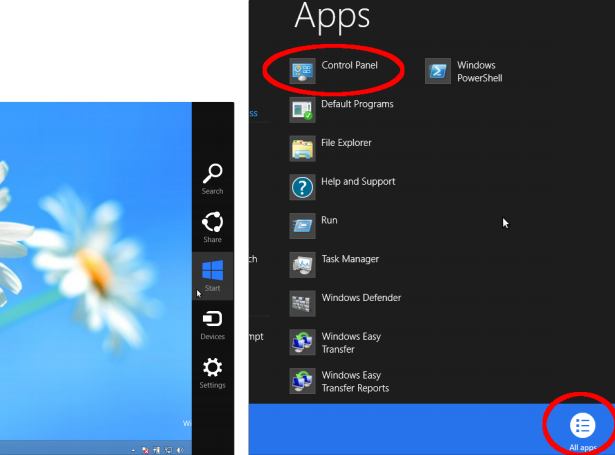
Microsoft Windows 8
2. Right-click and choose All apps.
3. Click on Control Panel.
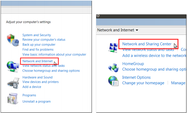
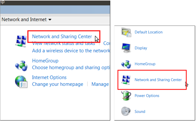
4. In category view, open Network and Internet.
5. Choose Network and Sharing Center.
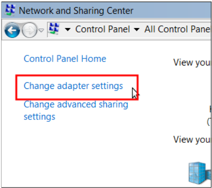
6. On the left side, open Change Adapter Settings.
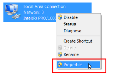
7. Disable any network connections you are not using to connect to the eGauge by right-clicking them and choosing Disable. This should be done for all wireless adapters when connected via Ethernet to the eGauge or HomePlug adapter.
8. Right-click the adapter you will be using to connect to the eGauge and choose Properties.
9. In the Properties window, click the item listed as Internet Protocol Version 4 (TCP/IPv4) and click the Properties button.
10. If Use the following IP address already contains values, write these down as they will be overwritten.
11. Click the radio button that says Use the following IP address and enter the following values:
IP address: 192.168.1.11
Subnet mask: 255.255.255.0
12. Click OK to save the changes and then click Close to close the properties window. To verify settings, right-click again on the adapter that was modified and choose Status and then Details. Look to see that IPv4 Address matches 192.168.1.11.
13. Access the eGauge at http://192.168.1.88. When done accessing the eGauge, revert any adapter’s properties that you have changed during this process.
Microsoft Windows 7
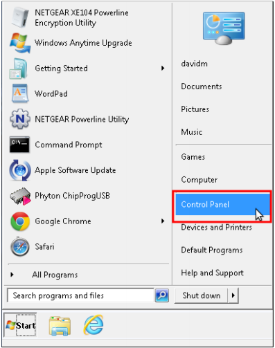
1. Open the Start Menu and choose Control Panel.
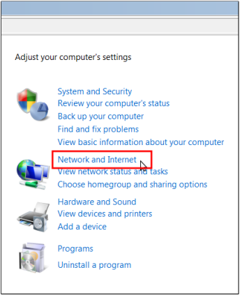
2. In category view, open Network and Internet.
3. Choose Network and Sharing Center.
4. On the left side, open Change Adapter Settings.

5. Disable any network connections you are not using to connect to the eGauge by right-clicking them and choosing Disable. This should be done for any wireless adapters when connected via Ethernet to the eGauge or HomePlug adapter.
6. Right-click the adapter you will be using to connect to the eGauge and choose Properties.
7. In the Properties window, click the item listed as Internet Protocol Version 4 (TCP/IPv4) and click the Properties button.

8. If Use the following IP address already contains values, write these down as they will be overwritten.
9. Click the radio button that says Use the following IP address and enter the following values:
IP address: 192.168.1.11
Subnet mask: 255.255.255.0
10. Click OK to save the changes and then click Close to close the properties window. To verify settings, right-click again on the adapter that was modified and choose Status and then Details. Look to see that IPv4 Address matches 192.168.1.11.
11. Access the eGauge at http://192.168.1.88. When done accessing the eGauge, revert any adapter’s properties that you have changed during this process.
Mac OS X (tested on Mountain Lion 10.7)
1. Click the network icon in the upper right hand corner of the screen and choose Open Network Preferences.

2. Click Wi-Fi on the left hand column and then Turn Wi-Fi Off.

3. Click Ethernet on the left hand column, and next to Configure IPv4 choose Manually from the drop down menu. If Manually is already selected, take note of all values as they will be overwritten and should be restored after this process.
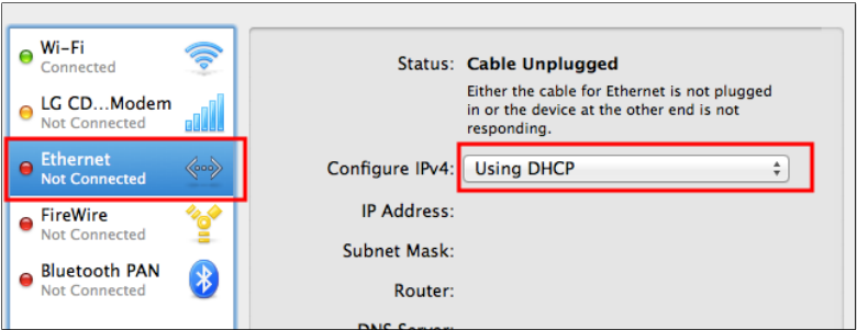
4. Enter the following information in the configuration boxes:
IP address: 192.168.1.11
Subnet mask: 255.255.255.0
5. Click Apply to save changes.
6. Access the eGauge at http://192.168.1.88. When done accessing the eGauge, revert any
adapter’s properties that you have changed during this process.
Linux/Unix
1. Open a terminal session
2. Locate the name of your network connections by using the command ifconfig. There should be a device such as athX, ethX, or wlanX where X is a number with information pertaining to the current IP address. Newer systems may use Predictable Interface Names, such as enoX, ensX, enpXsY, and so on.
3. Enter the following commands, where [eth con] is your Ethernet connection name and [wifi con] is your wireless connection name (if applicable).
sudo ifconfig [wifi con] down
sudo ifconfig [eth con] down
sudo ifconfig [eth con] 192.168.1.11 netmask 255.255.255.0
sudo ifconfig [eth con] up
4. The eGauge is now accessible at http://192.168.1.88.
Three-Phase installation tutorial
There are a number of considerations when installing an eGauge, including positioning of CTs, mounting the eGauge, and routing wiring appropriately. The video below discusses these and similar considerations, using visual examples. Of particular concern is determining the correct phasing relationship between the CTs and voltage references. The panel in the video is not live, and local electrical code should supersede any suggestions made in this video. eGauge does not recommend that untrained individuals open or operate inside of electrical enclosures.
Note that EG4xxx meters and EG30xx meters using a direct Ethernet connection must be installed in an external enclosure.
Surges and overvoltage
The eGauge is rated for overvoltage CAT III, covering installation on main distribution panels. Devices that experience a CAT III or lower surge may have internal, non-user replaceable fuses blown. Surges exceeding CAT III limits may not be repairable. Contact eGauge support at support@egauge.net to set up an inspection RMA if your device no longer powers on due to surge or overvoltage. Note that damage caused by overvoltage is not covered under warranty.

Monitoring High Voltage DC Loads
Overview
The EG4xxx meter features a low voltage terminal (Ldc) which can be used to measure 9-60Vdc (12-60Vdc is required to power the meter from the Ldc terminal). However, there are many monitoring applications where DC voltage exceeds 60Vdc. String-based inverter monitoring is probably the most common application. It's also common to have multiple DC voltage references, but the Ldc terminal can only support one measurement.
Using several EV1000 High Voltage Sensors and an ESH044 Sensor Hub, it's possible to measure higher DC voltages directly (up to 1000Vdc). This can be used anywhere there are multiple DC voltage measurements. Note that each EV1000 sensor uses a sensor port on the eGauge, so a single EG4xxx meter can support either 15 or 30 high voltage sensors (depending on meter model). As CTs also use sensor ports, the number of high voltage sensors used will likely be lower (so CTs can also be used).
This guide only applies to EG4xxx meters. Older EG30xx and eGauge2 meters do not support the EV1000 or CTid CTs.
Installation Considerations
There are a few general concerns when using EV1000 high voltage sensors:
1. EV1000 sensors must be connected directly to the DC voltage source. Make sure to follow all necessary safety precautions and code requirements for your area.
2. Sensor Hubs must be powered. Up to 2 hubs can be powered directly from the eGauge via the USB ports on the meter. For installations where more hubs are required or the USB ports are in use (e.g., for Modbus RTU communication) the hubs can be powered directly from a 5Vdc power supply.
3. All hardware must be installed in a suitably rated enclosure. eGauge Systems offers several powered enclosure kits which are suitable for this purpose. Most kits feature DIN rails (for mounting the eGauge meter and EV1000s securely) along with a powered receptacle and optional stepdown transformer (which can be used to power the 5Vdc supply for the sensor hubs and/or other supporting hardware).
Examples
The following are general examples which may be useful for planning a specific installation. Note that these examples may omit certain details (for example, not all ports are shown on the eGauge meter). These are intended to serve as guidelines only - always consult local code requirements when planning an installation.
Hardware appearance in the following diagrams may not reflect the actual size or layout of actual hardware. Refer to the product pages for actual measurements.
Configuration examples are correct for the diagram shown. Actual installations will likely use a different combination of ports, different CT types, and so on.
Monitoring multiple DC loads
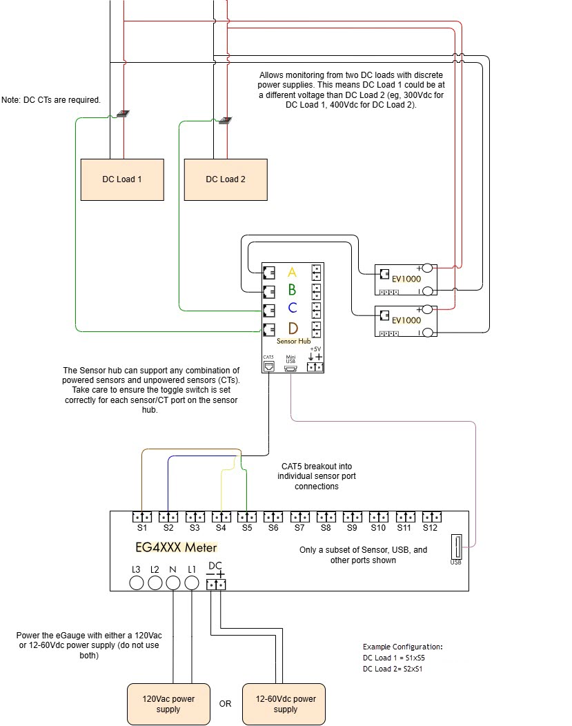
The meter configuration would be set as follows below. Your DC CTs may scan with different information depending on the model. For more information on CTid please see: Configuring CTid Sensors.
Sensor Hub and Sensors
RJ-11 wiring between Sensor Hub and Sensors
Please visit this article for general information on the eGauge Sensor Hub and compatible sensors.
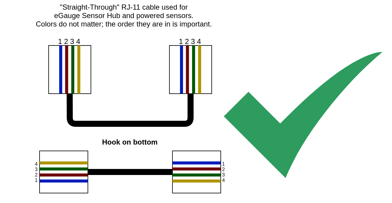
RJ-11 cables come in two varieties: "straight-through" and "reverse". Reverse is generally used in telephone systems, but the eGauge Sensor Hub uses "straight through" which is different. Using the incorrect style will result in failure to power the sensor and may lead to damage.
It is recommended only to extend the RJ-45 connection from the Sensor Hub to the eGauge meter sensor inputs. If extending the RJ-11 cable between the Sensor Hub and powered sensors is necessary, twisted pair RJ-11 should be used. Twisted pair RJ-11 is typically used in DSL modem connections. Ensure straight-through pinout is used as well.
The Sensor Hub uses "straight through" RJ-11 cables to connect the Sensor Hub to a powered sensor. This differs from "reversed" RJ-11 cables that are commonly used in telephone connections. It is a common misconception on which style is straight-through and reversed.
If using a cable that did not come with the sensor purchased from eGauge Systems, please ensure the wiring is done as "straight through" as depicted below.