| [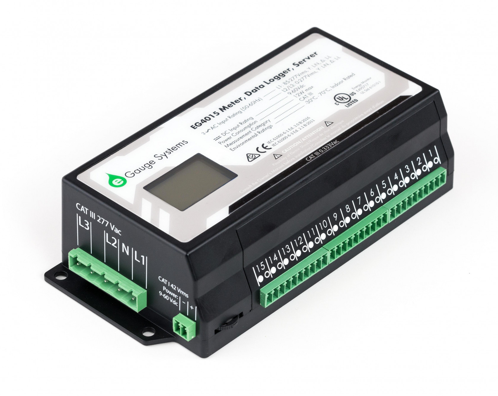](https://kb.egauge.net/uploads/images/gallery/2020-06/egauge-core.jpg) |
| *eGauge Core (EG4015)* |
| [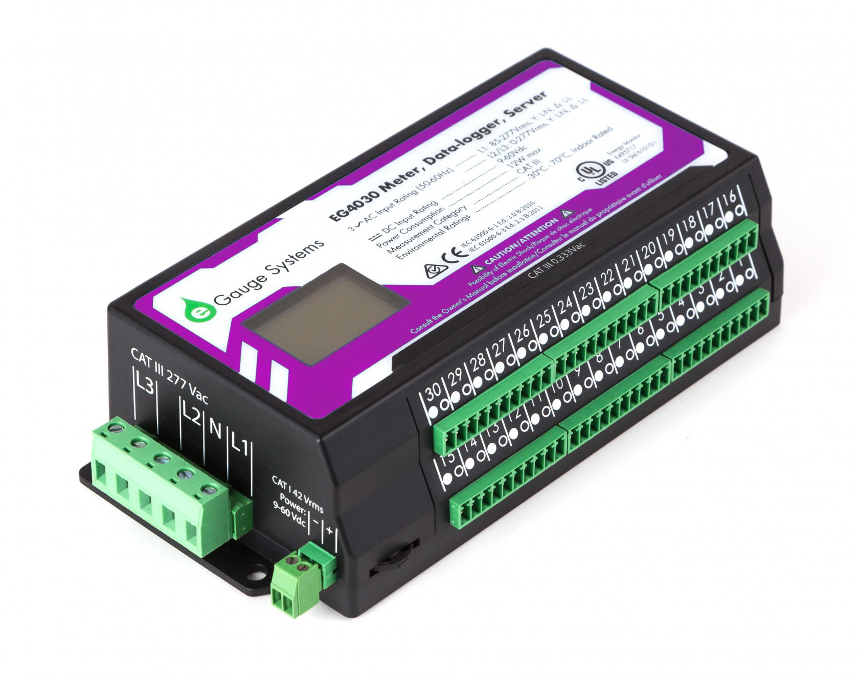](https://kb.egauge.net/uploads/images/gallery/2021-09/egauge-pro-eg4030.jpg) |
| *eGauge Pro (EG4030)* |
See the **[eGauge Meter Comparison Chart](https://kb.egauge.net/books/egauge-meter-documentation/page/meter-comparison-chart-%28difference-between-core-and-pro-meters%29 "eGauge Meter Comparison Chart")** for full side-by-side comparisons.
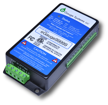
eGauge meters combines an energy meter, data logger, and a web server. This powerful combination lets you measure, store and retrieve data directly from the device or from a remote location. Not only does it calculate power (V, A, VAr, kWh, etc), but also data from optional sensors that assess flow rate, temperature, wind speed, and more. You can view historical and live data for up to 30 years with the unit’s convenient user interface (UI). The UI can be accessed on a local network or via the internet from a computer, tablet, or smartphone. Once connected, you have access to real-time values, long-term reports, an interactive graphical interface, and many other tools. The best part is that you pay nothing for the user interface because you retrieve data directly from your own eGauge hardware, not a cloud or 3rd party host.| [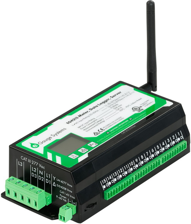](https://kb.egauge.net/uploads/images/gallery/2024-03/Jdoscreenshot-from-2024-03-07-15-08-40.png) | [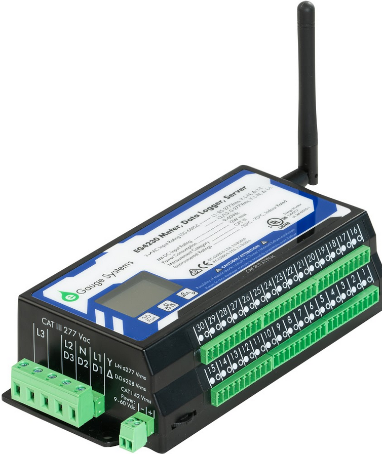](https://kb.egauge.net/uploads/images/gallery/2024-03/ll4screenshot-from-2024-03-07-15-09-35.png) |
| *eGauge Core WiFi* | *eGauge Pro WiFi* |
Ensure the WiFi antenna is connected and not within a metal or shielded enclosure that may block or interfere with the WiFi signal.
See the [Installation Overview Tips](https://kb.egauge.net/books/egauge-meter-configuration/page/installation-overview-tips-%28start-here%29 "Installation Overview Tips") to get started with general installation and setup. To connect the meter to WiFi, follow the [EG42xx WiFi Connection setup article](https://kb.egauge.net/books/egauge-meter-communication/page/eg42xx-wifi-connection). ## Documents - [Installation Overview and Tips](https://kb.egauge.net/books/egauge-meter-configuration/page/installation-overview-tips-%28start-here%29) - [EG4xxx Owner's Manual](https://www.egauge.net/media/support/docs/eg4xxx-manual.pdf "EG4xxx Owner's Manual") - [eGauge Configuration Guide](https://www.egauge.net/media/support/docs/config-guide.pdf "eGauge Config Guide") - [EG4215 Data Sheet](https://www.egauge.net/media/support/docs/EG4215-datasheet-WEB.pdf) - [EG4230 Data Sheet](https://www.egauge.net/media/support/docs/EG4230-datasheet-WEB.pdf) ## Related Information - [EG42xx WiFi Connection setup article](https://kb.egauge.net/books/egauge-meter-communication/page/eg42xx-wifi-connection) - [Meter Comparison Guide](https://kb.egauge.net/books/egauge-meter-documentation/page/meter-comparison-chart-%28difference-between-core-and-pro-meters%29 "eGauge Meter Comparison Guide") - [Related Meter Products](https://kb.egauge.net/books/egauge-hardware-product-pages/chapter/egauge-meters) - [eGauge Meter Configuration](https://kb.egauge.net/books/egauge-meter-configuration) # Meter Accuracy Certificate ##### [ Visit the online store page](https://store.egauge.net/accuracy_certificate "Visit the online store now!") The eGauge Meter Accuracy Certificate may be purchased with an eGauge meter to show the test conditions and results of the specific eGauge meter hardware. This document provides compliance of ANSI C12.20 0.5% revenue grade accuracy.Notice: The eGauge Meter Accuracy Certificate must be requested at the time of meter purchase. Meters cannot have a certificate generated once they are shipped.
| [](https://kb.egauge.net/uploads/images/gallery/2020-06/accuracy-certificate.jpg) |
| *Meter Accuracy Certificate* |
Notice: The 3-year Warranty Extension must be purchased at the time of meter sale. Warranty extensions cannot be applied to devices after they are purchased and shipped. Warranty does not over physical or environmental damage, only manufacturer hardware failure.
## Related Information - [eGauge Warranty Policy](https://www.egauge.net/policy/#warranty-agreement) - [eGauge Meters Products](https://kb.egauge.net/books/egauge-hardware-product-pages/chapter/egauge-meters) # Meter: eGauge Pro (HomePlug, discontinued) ##### Model: EG4130The EG4130 has been discontinued and replaced with the [**EG4030**](https://egauge.net/support/m/eg4030 "EG4030"). If HomePlug communication on a Pro meter is needed, a HomePlug adapter may be connected to the Ethernet port of the EG4030.
The eGauge Pro (EG4130) is the Pro version of the EG4xxx meter line. It has 30 sensor inputs and integrated HomePlug communication. See the **[Meter Comparison Chart](https://kb.egauge.net/books/egauge-meter-documentation/page/meter-comparison-chart-%28difference-between-core-and-pro-meters%29 "meter-comparison-chart")** for the different versions of the EG4xxx meter line and what is the best fit. The eGauge Pro combines an energy meter, data logger, and a web server. This powerful combination lets you measure, store and retrieve data directly from the device or from a remote location. Not only does it calculate power (V, A, VAr, kWh, etc), but also data from optional sensors that assess flow rate, temperature, wind speed, and more. You can view historical and live data for up to 30 years with the unit’s convenient user interface (UI). The UI can be accessed on a local network or via the internet from a computer, tablet, or smartphone. Once connected, you have access to real-time values, long-term reports, an interactive graphical interface, and many other tools. The best part is that you pay nothing for the user interface because you retrieve data directly from your own eGauge hardware, not a cloud or 3rd party host.| [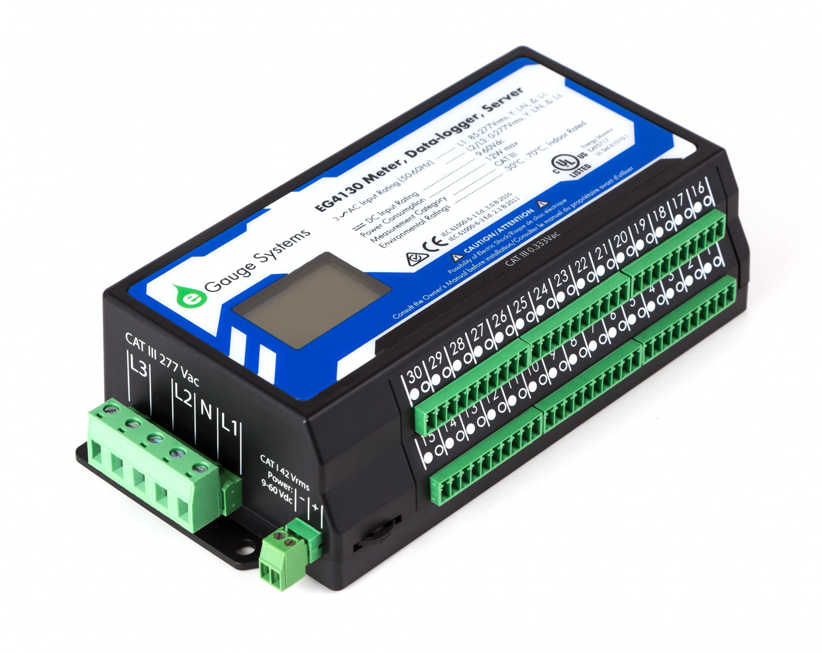](https://kb.egauge.net/uploads/images/gallery/2020-06/egauge-pro_1.jpg) |
| *eGauge Pro (EG4130)* |
This is a discontinued product. eGauge Systems no longer offers HomePlug-compatible devices. If wireless communication is required, please utilize the **[WiFi-enabled EG42xx series meter](https://kb.egauge.net/books/egauge-hardware-product-pages/page/meter-egauge-core-and-pro-with-wifi)**.
##### [ Visit the online store page](https://store.egauge.net/egauge-core "Visit the online store now!") ##### Model: EG4115 The eGauge Core Residential (EG4115) is the Pro version of the EG4xxx meter line. It has 15 sensor inputs and integrated HomePlug power-line communication. See the **[Meter Comparison Chart](https://kb.egauge.net/books/egauge-meter-documentation/page/meter-comparison-chart-%28difference-between-core-and-pro-meters%29 "meter-comparison-chart")** for the different versions of the EG4xxx meter line and what is the best fit.The eGauge Core Residential has integrated HomePlug (power-line) communication. If power-line communication is not needed, you may use the standard **[eGauge Core (EG4015)](https://kb.egauge.net/books/egauge-hardware-product-pages/page/egauge-core "eGauge Core Article")** without power-line communication. **[eGauge Meter Comparison Chart](https://kb.egauge.net/books/egauge-meter-documentation/page/meter-comparison-chart-%28difference-between-core-and-pro-meters%29 "eGauge Meter Comparison Chart")** for full side-by-side comparisons.
| [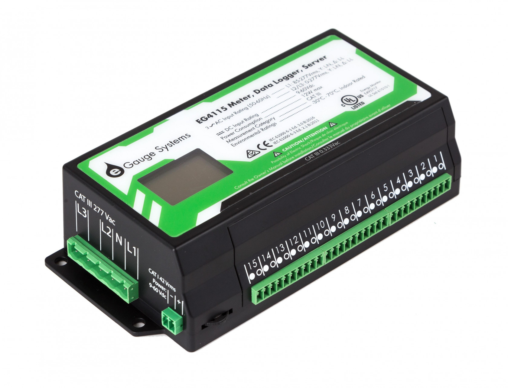](https://kb.egauge.net/uploads/images/gallery/2020-06/core-residential.jpg) |
| *eGauge Core Residential (EG4115)* |
| [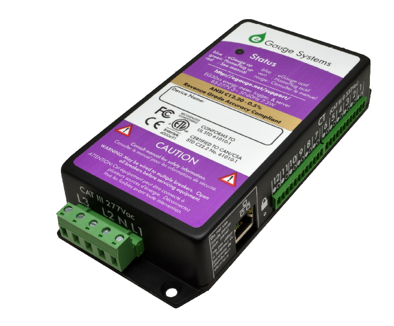](https://kb.egauge.net/uploads/images/gallery/2020-06/eg30xx-purple.png) | [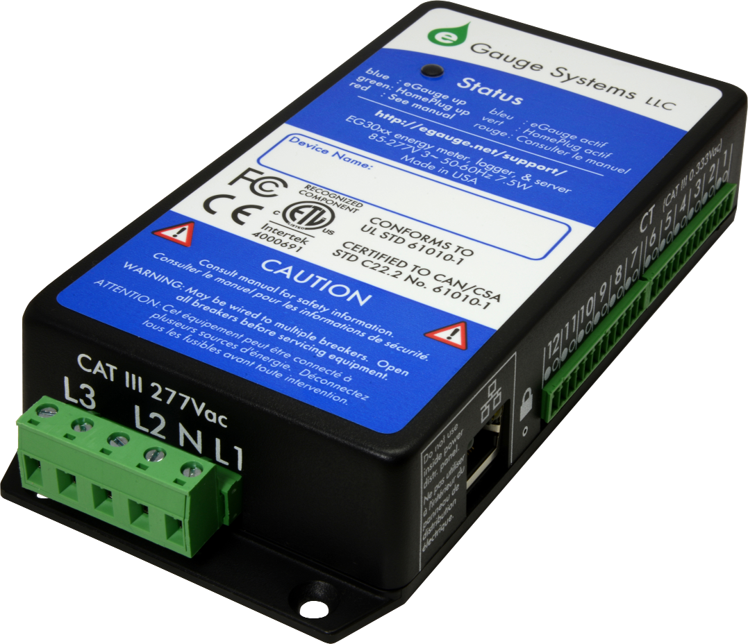](https://kb.egauge.net/uploads/images/gallery/2020-06/eg30xx-blue.png) |
| *Model: EG30xx (Purple Label)* | *Model: EG30xx (Blue Label)* |
| [](https://kb.egauge.net/uploads/images/gallery/2020-06/egauge2.png) |
| *Model: eGauge2 (note: no Ethernet port)* |
The ECS20 and ECS36 CTs may be used to measure bare (non insulated) conductors and on service entrance conductors up to 600V. ECS09 are rated for insulated conductors on CAT III up to 250V
AC split-core CTs measures the amperage of a conductor on an AC (alternating current) system. Combined with voltage measurements, this allows calculation of power and energy values. AC CTs provided by eGauge are split-core, meaning they can be wrapped around a conductor instead of having to disconnect the conductor and feed it through the CT. The eGauge ECS CT series have CTid technology and contain a locator LED that can be blinked to identify which CT is connected to a given sensor port. This is useful if the CT leads cannot be traced. eGauge ECS CTs are also UL2808 certified and may be used on bare metal or insulated wires up to 600V in Category IV environments. ECS CTs are available with 1% accuracy (ECS*xx*-yyy) and 0.5% accuracy *(ECSxx-yyy-R).*
| |
| *eGauge ECS Split-Core AC CTs. The CTid LED can be seen through the transparent window on the bottom of the CT.* |
The ECS series CTs are a CTid enabled sensor. They are physically installed in the same manner as conventional CTs, but are configured using CTid. See **[this article](https://kb.egauge.net/books/egauge-meter-configuration/page/configuring-ctid-enabled-sensors)** for more information on configuring CTid enabled sensors.
Point the arrow on the CT in the same direction of the normal current flow.
See the [Installation Overview Tips](https://kb.egauge.net/books/egauge-meter-configuration/page/installation-overview-tips-%28start-here%29 "Installation Overview Tips") to get started. 1.To reduce risk of electric shock, open or disconnect circuits from the power distribution system (or service) of the building before installing or serving CTs.
2. Open the CT by gently pulling on the latch and then rotating the top open. **Do not touch the polished ferrite core surfaces**. Any oils or debris in that area worsens accuracy. 3. Slide the CT over the conductor of the circuit to be measured. Make sure the arrow on the CT points in the direction of the normal current flow (the current flow that should yield a positive power reading). 4. Close the CT by gently pushing down on top of the CT until the latch engages. 5. Verify that the CT is fully closed by squeezing together the top and bottom parts of the CT. 6. Optional: secure the CT to the conductor with a cable tie. 7. Route the twisted pair wires of the CT to the meter such that they do not directly contact live terminals or bus bars. 8. Plug the 2-pin terminal at the end of the twisted pair wires into an unused port on the meter. 9. When connected to an EG4xxx meter, use the [CTid® scanning feature](https://kb.egauge.net/books/egauge-meter-configuration/page/configuring-ctid-enabled-sensors) to automatically detect the sensor type and its current rating. If using an older model meter, use the drop-down method to [Configure the sensor input](https://kb.egauge.net/books/egauge-meter-configuration/page/initial-configuration-steps).| [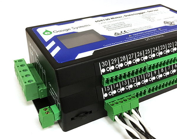](https://kb.egauge.net/uploads/images/gallery/2021-10/qsg-ct-plugs.jpg) |
| *CTs connected to eGauge meter.* |
| [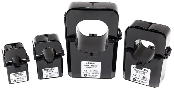](https://kb.egauge.net/uploads/images/gallery/2020-02/image-1582835601115.png) |
| *Standard split-core CTs in multiple sizes* |
To reduce risk of electric shock, open or disconnect circuits from the power distribution system (or service) of the building before installing or serving CTs.
2. Open the CT by gently pulling on the latch and then rotating the top open. **Do not touch the polished ferrite core surfaces**. Any oils or debris in that area worsens accuracy. 3. Slide the CT over the conductor of the circuit to be measured. Make sure the sticker on the CT points in the direction of the primary current flow (the current flow that should yield a positive power reading). 4. Close the CT by gently pushing down on top of the CT until the latch engages. **Some CTs require 2 clicks to fully shut.** 5. Verify that the CT is fully closed by squeezing together the top and bottom parts of the CT. 6. Optional: secure the CT to the conductor with a cable tie. 7. Route the twisted pair wires of the CT to the meter such that they do not directly contact live terminals or bus bars. 8. Plug the 2-pin terminal at the end of the twisted pair wires into an unused port on the meter. 9. [Configure the sensor input](https://kb.egauge.net/books/egauge-meter-configuration/page/initial-configuration-steps) in the meter interface and complete the general configuration.| [](https://kb.egauge.net/uploads/images/gallery/2021-10/qsg-ct-plugs.jpg) |
| *CTs connected to eGauge meter.* |
| [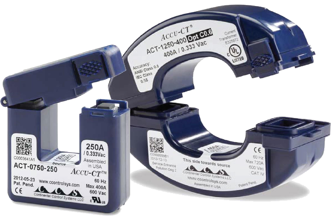](https://kb.egauge.net/uploads/images/gallery/2020-02/image-1582835634199.png) |
| *C0.6 certified high-accuracy CTs* |
To reduce risk of electric shock, open or disconnect circuits from the power distribution system (or service) of the building before installing or serving CTs.
2. Open the CT by gently squeezing the textured latch and then rotating the top open. **Do not touch the polished ferrite core surfaces**. Any oils or debris in that area worsens accuracy. 3. Slide the CT over the conductor of the circuit to be measured. **Make sure the sticker on the CT points in the direction of the primary current flow (the current flow that should yield a positive power reading).** 4. Close the CT by gently pushing down on top of the CT until the latch engages. 5. Verify that the CT is fully closed by squeezing together the top and bottom parts of the CT. 6. Optional: secure the CT to the conductor with a cable tie. 7. Route the twisted pair wires of the CT to the meter such that they do not directly contact live terminals or bus bars. 8. Plug the 2-pin terminal at the end of the twisted pair wires into an unused port on the meter. 9. [Configure the sensor input](https://kb.egauge.net/books/egauge-meter-configuration/page/initial-configuration-steps) in the meter interface and complete the general configuration.| [](https://kb.egauge.net/uploads/images/gallery/2021-10/qsg-ct-plugs.jpg) |
| *CTs connected to eGauge meter.* |
Rope CTs are designed for 20-30 amps or greater load. Lower amperage results in lower accuracy readings.
Face the arrow on the rope towards what you want to measure. Positive power polarity when power is *against* the arrow, and negative when it is the same direction the arrow points.
The position of the Rope CT on the conductor affects accuracy. See [this article](https://kb.egauge.net/books/ct-faqs-and-other-information-f71/page/rope-ct-positioning-guide) for more information.
#### Why use a Rope CT? Rope CTs are excellent for bus-bars and large switch-gear applications that standard split-core CTs cannot fit around. Rope CTs are flexible and easy to install but require a minimum amperage of approximately 30A for accuracy.| [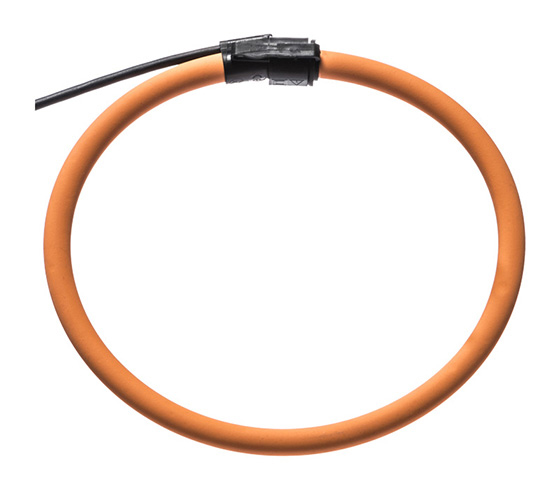](https://kb.egauge.net/uploads/images/gallery/2020-02/image-1582830017390.png) |
| *Rope CT* |
To reduce risk of electric shock, open or disconnect circuits from the power distribution system (or service) of the building before installing or serving CTs.
2. Open the rope CT by gently pulling squeezing the latch and pulling the end of the rope CT out. **Do not touch the inside surfaces where the CT opens**. Any oils or debris in that area worsens accuracy. 3. Wrap the rope CT over the conductor of the circuit to be measured. Make sure the arrow on the rope CT points in the direction of the primary current flow (the current flow that should yield a positive power reading). 4. Close the rope CT by gently squeezing the latch and inserting the other end inside the latching end and release the latch. 5. Verify that the rope CT is fully closed. 6. Optional: secure the CT to the conductor with a cable tie. 7. Route the twisted pair wires of the CT to the meter such that they do not directly contact live terminals or bus bars. 8. Plug the 2-pin terminal at the end of the twisted pair wires into an unused port on the meter. 9. [Configure the sensor input](https://kb.egauge.net/books/egauge-meter-configuration/page/initial-configuration-steps) in the meter interface and complete the general configuration.| [](https://kb.egauge.net/uploads/images/gallery/2021-10/qsg-ct-plugs.jpg) |
| *CTs connected to eGauge meter*. |
This article is for the **ERA-*XXX*-*YYYY* CTid enabled Rope CT**. For the non-CTid enabled ropes (RCT-*XXX*-*YYYY*) please visit **[this article](https://kb.egauge.net/books/egauge-hardware-product-pages/page/ac-rope-cts-%28rogowski-coil%29)**. In the upcoming future all Rope CTs will be CTid-enabled. Check the model number on the tag of the Rope CT to verify which version you have. CTid enabled Ropes start with ERA, and ones without CTid start with RCT. Information on configuring CTid sensors can be **[found here](https://kb.egauge.net/books/egauge-meter-configuration/page/configuring-ctid-enabled-sensors)**.
Rope CTs (technically called Rogowski Coils) are large, flexible sensors for monitoring current like split-core CTs. Rope CTs are installed similar to standard split-core CTs, where a connector on the rope allows it to be opened and placed around a conductor without needing to thread the conductor through it. For pricing and available models, visit the [online store](https://store.egauge.net/Rope-CTs). The ERA Rope CT contains CTid. It is the same as the RCT-*XXX*-*YYYY* model but has a different style connector and contains CTid for auto-detection and has an onboard LED that can be used to identify which CT is connected to a given sensor port, which can be useful if the CT leads cannot be traced from the meter to the conductors being monitored. The CTid-enabled Ropes are available in sizes of 106 mm (2775 A max), 178 mm (2775 A or 6935 A max), and 271 mm (6935 A max). Please see the [online store](https://store.egauge.net/Rope-CTID) or [data sheet](https://www.egauge.net/media/support/docs/ERA-xxx-yyyy-datasheet-WEB.pdf) for available combinations.Rope CTs are designed for 20-30 amps or greater load. Lower amperage results in lower accuracy readings.
Face the arrow on the rope towards what you want to measure. Positive power polarity when power is *against* the arrow, and negative when it is the same direction the arrow points.
The position of the Rope CT on the conductor affects accuracy. See [this article](https://kb.egauge.net/books/ct-faqs-and-other-information-f71/page/rope-ct-positioning-guide) for more information.
#### Why use a Rope CT? Rope CTs are excellent for bus-bars and large switch-gear applications that standard split-core CTs cannot fit around. Rope CTs are flexible and easy to install but require a minimum amperage of approximately 30A for accuracy.| [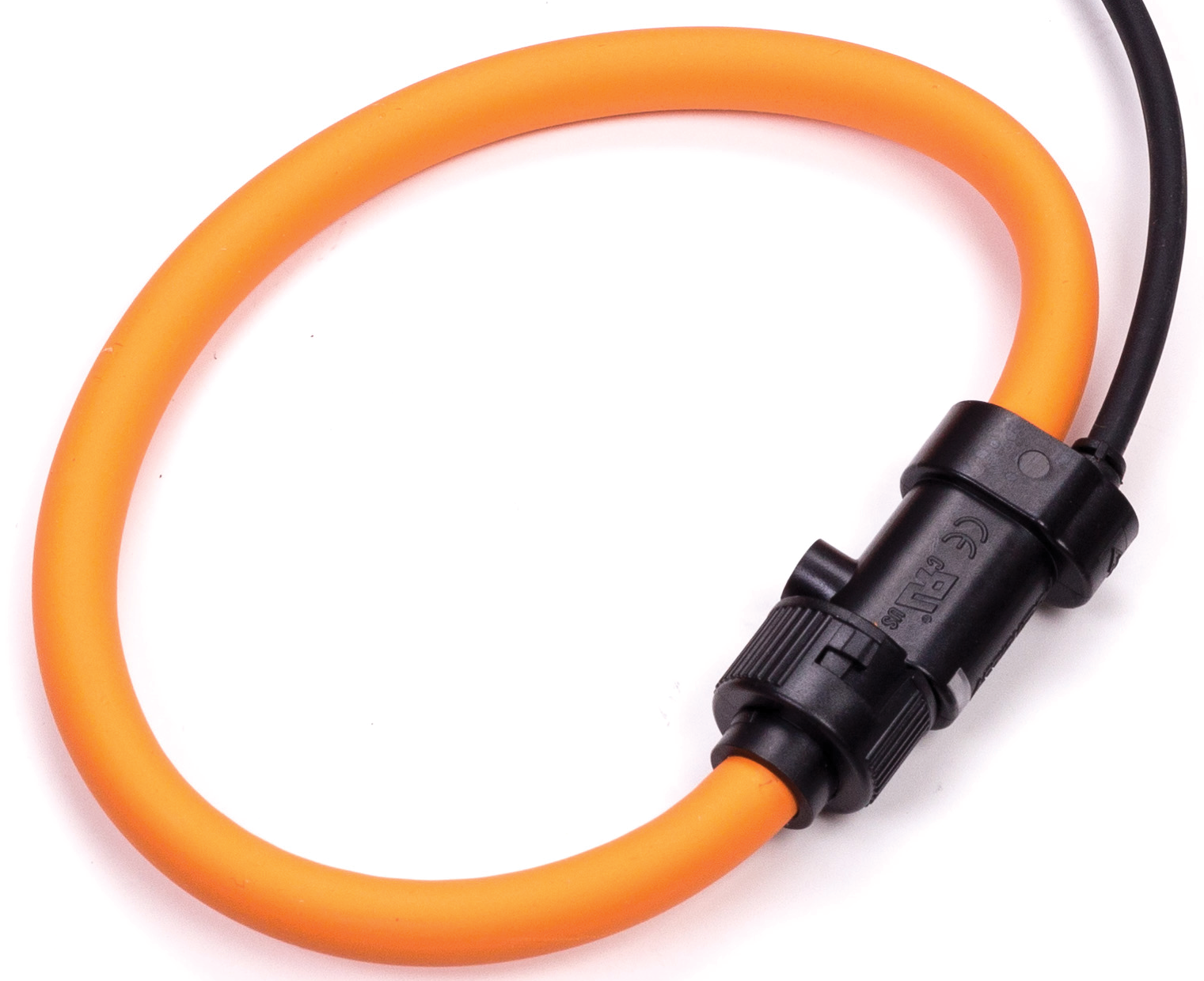](https://kb.egauge.net/uploads/images/gallery/2021-01/image-1610998278713.png) |
| *ERA-106-2775 Rope CT* |
The ERA-*XXX*-*YYYY* is a CTid enabled sensor and is configured differently than conventional CTs. See **[this article](https://kb.egauge.net/books/egauge-meter-configuration/page/configuring-ctid-enabled-sensors)** for more information on configuring CTid enabled sensors.
See the [Installation Overview Tips](https://kb.egauge.net/books/egauge-meter-configuration/page/installation-overview-tips-%28start-here%29 "Installation Overview Tips") to get started. 1.To reduce risk of electric shock, open or disconnect circuits from the power distribution system (or service) of the building before installing or serving CTs.
2. Open the rope CT by gripping and twisting the bayonet connector and pulling the end of the rope CT out. **Do not touch the inside surfaces where the CT opens**. Any oils or debris in that area worsens accuracy. 3. Wrap the rope CT over the conductor of the circuit to be measured. Make sure the arrow on the rope CT points in the direction of the primary current flow (the current flow that should yield a positive power reading). 4. Close the rope CT by gently squeezing the latch and inserting the other end inside the latching end and release the latch. 5. Verify that the rope CT is fully closed. 6. Optional: secure the CT to the conductor with a cable tie. 7. Route the twisted pair wires of the CT to the meter such that they do not directly contact live terminals or bus bars. 8. Plug the 2-pin terminal at the end of the twisted pair wires into an unused port on the meter. 9. When connected to an EG4xxx meter, use the [CTid® scanning feature](https://kb.egauge.net/books/egauge-meter-configuration/page/configuring-ctid-enabled-sensors) to automatically detect the sensor type and its current rating. If using an older model meter, use the drop-down method to [Configure the sensor input](https://kb.egauge.net/books/egauge-meter-configuration/page/initial-configuration-steps).| [](https://kb.egauge.net/uploads/images/gallery/2021-10/qsg-ct-plugs.jpg) |
| *CTs connected to eGauge meter.* |
| [](https://kb.egauge.net/uploads/images/gallery/2020-02/image-1582839679988.png) |
| *Large 2" split-Core CT* |
To reduce risk of electric shock, open or disconnect circuits from the power distribution system (or service) of the building before installing or serving CTs.
2. Open the CT by holding the bottom part of the CT still and pulling the top part off. **Do not touch the polished ferrite core surfaces**. Any oils or debris in that area worsens accuracy. 3. Slide the CT over the conductor of the circuit to be measured. Make sure the sticker on the CT points in the direction of the primary current flow (the current flow that should yield a positive power reading). 4. Close the CT by gently pushing the top part of the CT back onto the bottom part and it clicks shut. 5. Verify that the CT is fully closed by squeezing together the top and bottom parts of the CT. 6. Optional: secure the CT to the conductor with a cable tie. 7. Route the twisted pair wires of the CT to the meter such that they do not directly contact live terminals or bus bars. 8. Plug the 2-pin terminal at the end of the twisted pair wires into an unused port on the meter. 9. [Configure the sensor input](https://kb.egauge.net/books/egauge-meter-configuration/page/initial-configuration-steps) in the meter interface and complete the general configuration.| [](https://kb.egauge.net/uploads/images/gallery/2021-10/qsg-ct-plugs.jpg) |
| *CTs connected to eGauge meter.* |
| [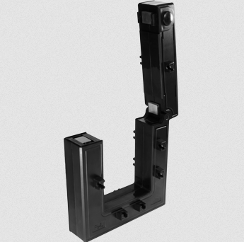](https://kb.egauge.net/uploads/images/gallery/2022-09/image-1662762138281.png) |
| *AcuCT-3135R* |
To reduce risk of electric shock, open or disconnect circuits from the power distribution system (or service) of the building before installing or serving CTs. Ensure any mounting is performed in compliance with all local and national electrical codes.
2. Open the CT by gently squeezing the latch buttons (circular buttons with an up arrow on the side opposite the hinge, see below for an image). **Do not touch the polished ferrite core surfaces**. Any oils or debris in that area worsens accuracy. 3. Slide the CT over the conductor of the circuit to be measured. **Make sure the arrow on the bottom of the CT points in the same direction of the primary current flow (the current flow that should yield a positive power reading).** 4. Close the CT by gently pushing down on top of the CT until the latch engages. The CT may click twice. 5. Verify that the CT is fully closed by squeezing together the top and bottom parts of the CT. 6. Optional: secure the CT using the mounting options. 7. Route the twisted pair wires of the CT to the meter such that they do not directly contact live terminals or bus bars. 8. Plug the 2-pin terminal at the end of the twisted pair wires into an unused port on the meter. 9. [Configure the sensor input](https://kb.egauge.net/books/egauge-meter-configuration/page/initial-configuration-steps) in the meter interface and complete the general configuration.| [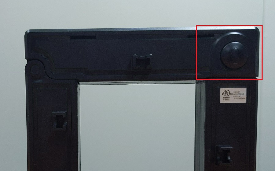](https://kb.egauge.net/uploads/images/gallery/2022-09/image-1663008010419.jpg) |
| *AcuCT-3135R latch button to open CT window, one on each side* |
| [](https://kb.egauge.net/uploads/images/gallery/2021-10/qsg-ct-plugs.jpg) |
| *CTs connected to eGauge meter.* |
Do not attempt to use mounting accessories to have the CTs weight held by the conductor being measured. The CT should be resting or mounted directly to a surface.
AcuCT-3135R come with mounting parts that may be used to secure the CT. The original manufacturer's mounting information may be found [here](https://www.egauge.net/media/support/docs/acuct-3135r-mounting.pdf). Busbar or Cable: 1. Place the screw caps at the end of the screws 2. Position the washer on the screw to the desired position on the screw 3. Insert washer into the small opening located near the window of the CT so that the screw cap is touching busbar/cable 4. Ensure that the screw caps are firmly securing the busbar and cable For mounting the CT on a surface, the following should be applied: 1. Place the mounting clips in the slots located by the removable top portion 2. Ensure mounting clips are securely placed in the slots 3. Using four screws (not included), place the screws through the mounting clips and tighten to attach to surface
|
eGauge DC CTs require a **[Sensor Hub](https://kb.egauge.net/books/egauge-hardware-product-pages/page/sensor-hub-%28esh044%29)** and are compatible with EG4xxx (Core and Pro) series. Legacy model meters (eGauge2, EG30xx) are not compatible.
| ||
| *eGauge Split-Core DC CT model ESD-016-0050. The CTid LED can be seen on the bottom of the CT illuminated in blue.* |
When current flows with the direction of the arrow, a positive amperage will be read. When current flows against the arrow, the amperage will read negative.
Be sure to see the [Installation Overview Tips](https://kb.egauge.net/books/egauge-meter-configuration/page/installation-overview-tips-%28start-here%29 "Installation Overview Tips") to get started. 1. To reduce risk of electric shock, open or disconnect circuits from the power distribution system (or service) of the building before installing or serving CTs. 2. Open the CT by gently pulling on the latch and then rotating the top open. **Do not touch the polished ferrite core surfaces**. Any oils or debris in that area worsens accuracy. 3. Slide the CT over the conductor of the circuit to be measured. Make sure the arrow on the CT points in the direction of the primary current flow (the current flow that should yield a positive power reading). 4. Close the CT by gently pushing down on top of the CT until the latch engages. 5. Verify that the CT is fully closed by squeezing together the top and bottom parts of the CT. 6. Optional: secure the CT to the conductor with a cable tie. 7. Route the RJ-11 cable of the CT to the Sensor Hub such that they do not directly contact live terminals or bus bars. 8. Follow [these instructions](https://kb.egauge.net/link/174#bkmrk-assembly%2Finstallatio) for Sensor Hub connection. Note: The DC CT is a **powered sensor** and the Sensor Hub requires +5V or a USB for power (the USB port on the eGauge meter may be used for this). 9. Use the [CTid® scanning feature](https://kb.egauge.net/books/egauge-meter-configuration/page/configuring-ctid-enabled-sensors) to automatically detect the sensor type and its current rating. ## Documents - [ESD-xxx-yyyyy Spec Sheet](https://www.egauge.net/media/support/docs/WEB-ESD-xxx-yyyy.pdf) ## Related Information - [CT Selection Guide](https://kb.egauge.net/books/ac-and-dc-cts/page/ct-selection-guide "CT selection guide") - [Sensor Hub Product Page](https://kb.egauge.net/books/egauge-hardware-product-pages/page/sensor-hub-%28esh044%29) - [Configuring CTid-enabled Sensors](https://kb.egauge.net/books/egauge-meter-configuration/page/configuring-ctid-enabled-sensors) # DC (Direct Current) CTs ##### ##### [ Visit the online store page](https://store.egauge.net/DC_current_transformers "Visit the online store now!") DC CTs measure Direct Current, as opposed to Alternating Current like standard split-core CTs monitor. Direct Current CTs are available in both split-core and solid-core versions. The DC CTs currently offered are Hall Effect style, uni-directional and require a 12Vdc power supply and special leads provided by eGauge. For pricing and available models, see the [online store.](https://store.egauge.net/DC_current_transformers)Please see the [**wiring information sheet**](https://kb.egauge.net/attachments/12) before installing. Use of special leads (provided) are required for use with the eGauge. Damage may occur if installed without leads or improperly.
| [](https://kb.egauge.net/uploads/images/gallery/2020-02/image-1582832315062.png) | [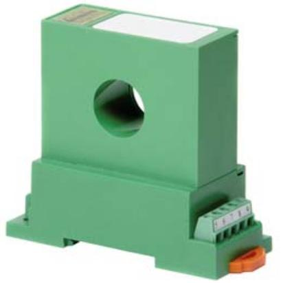](https://kb.egauge.net/uploads/images/gallery/2020-02/image-1582832323146.png) |
| *Split-core DC CT* | *Solid-core DC CT* |
The DC CT outputs 4-20mA and requires special leads to convert the signal. Damage may occur if installed without leads or improperly.
- The manufacturer offers both 12Vdc and 24Vdc versions; eGauge supplies the 12Vdc version. - The direction of current matters; the DC CT will read up to 100% of the current rating if current flows in the "X" and out the "O" side; reversing this will cause the DC CT to read at maximum 20% of the current rating. 1.To reduce risk of electric shock, open or disconnect circuits from the power distribution system (or service) of the building before installing or serving CTs.
2. If using a split-core CT, twist the orange knob to open the CT and gently pull the ends apart. **Do not touch the polished ferrite core surfaces**. Any oils or debris in that area worsens accuracy. 3. Slide the CT around the conductor of the circuit to be measured. Make sure the primary current flow direction enters the side marked "X" and out of the side marked "O". 4. If using a split-core CT, close the CT by gently pushing the ends of the CT together and twisting the knob back to the locked position. 5. Verify that the CT is fully closed. 6. Optional: secure the CT to the conductor with a cable tie. 7. Wire the power supply and output leads to the DC CT terminals as described in [this document.](https://kb.egauge.net/attachments/12) 8. Route the twisted pair wires of the CT to the meter such that they do not directly contact live terminals or bus bars. 9. Plug the 2-pin terminal at the end of the twisted pair wires into an unused port on the meter. 10. [Configure the sensor input](https://kb.egauge.net/books/egauge-meter-configuration/page/initial-configuration-steps) in the meter interface and complete the general configuration.| [](https://kb.egauge.net/uploads/images/gallery/2021-10/qsg-ct-plugs.jpg) |
| *CTs connected to eGauge meter*. |
Requires the [**eGauge Sensor Hub**](https://kb.egauge.net/books/egauge-hardware-product-pages/page/sensor-hub-%28esh044%29 "eGauge Sensor Hub") and eGauge model EG4xxx (Pro or Core), not compatible with older model units.
Only use straight-through RJ-11 cables to connect powered sensors to the Sensor Hub. Telephone systems generally use "reverse" style RJ-11 cables which are incompatible with the Sensor Hub. See **[this article](https://kb.egauge.net/books/egauge-installation/page/rj-11-wiring-between-sensor-hub-and-sensors)** for more information on verifying the correct RJ-11 wiring. Every Sensor Hub compatible sensor sold by eGauge Systems comes with a straight-through RJ-11 cable.
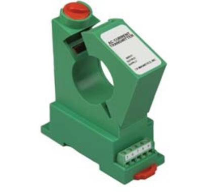
The eGauge Pulse Sensor is used in conjunction with the [Sensor Hub](https://kb.egauge.net/books/sensors/page/sensor-hub-%28esh044%29) and an EG4xxx model meter (Core or Pro) to record pulse output data from devices such as water and gas meters. The Pulse Sensor can accept standard 2-wire pulse outputs or 3-wire 5-volt Hall effect pulse outputs. [See our Sensors product introduction video here](https://www.youtube.com/watch?v=6D82guIQP50&feature=youtu.be).| [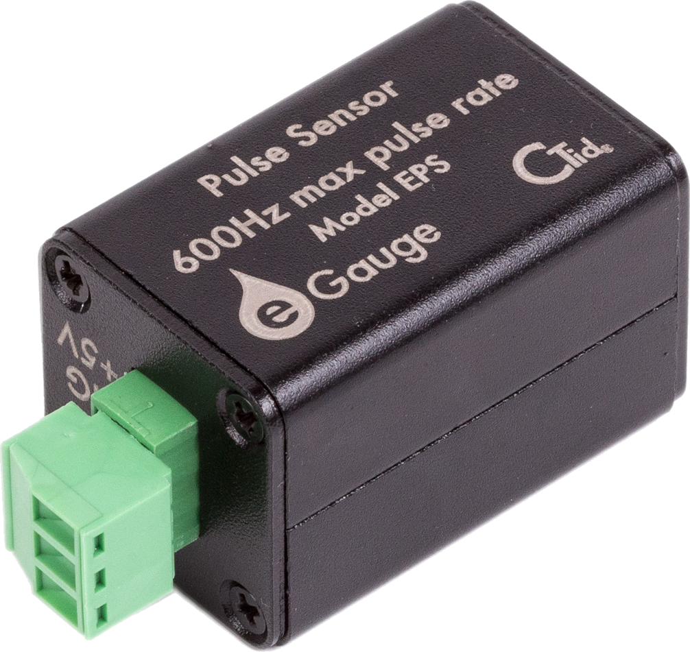](https://kb.egauge.net/uploads/images/gallery/2020-02/pulse-sensor-1006x951-transparent.png) | [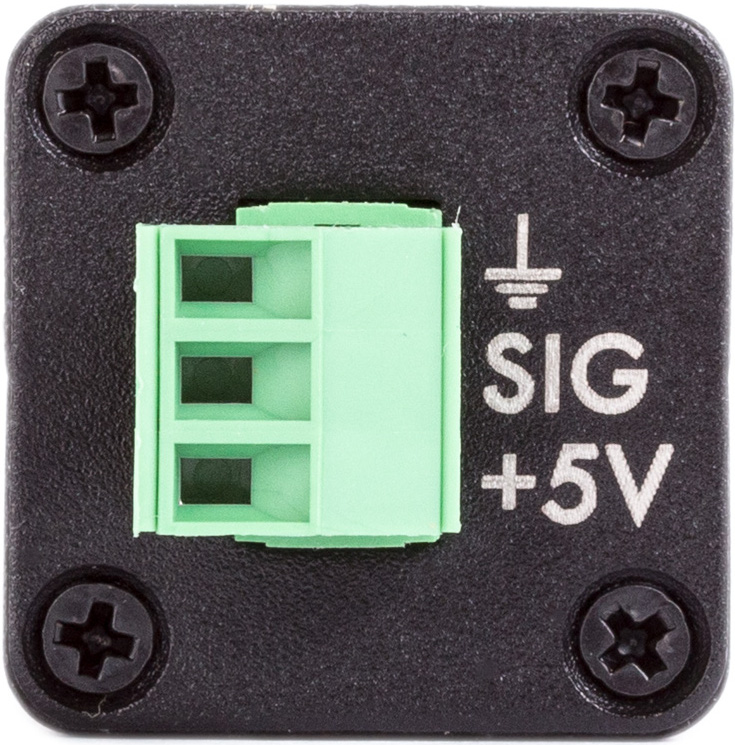](https://kb.egauge.net/uploads/images/gallery/2020-02/pulse-topdown.png) | [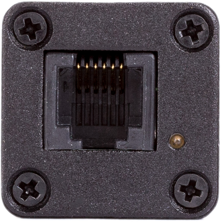](https://kb.egauge.net/uploads/images/gallery/2020-02/sensor-rj11.png) |
| *Side view of EPS* | *Front view of EPS with connections* | *Back-side of EPS with RJ-11 port and CTid locator LED* |
Requires the [**eGauge Sensor Hub**](https://kb.egauge.net/books/egauge-hardware-product-pages/page/sensor-hub-%28esh044%29 "eGauge Sensor Hub") and eGauge model EG4xxx (Pro or Core), not compatible with older model units.
Analog sensors require ≤ 50Ω output.
Only use straight-through RJ-11 cables to connect powered sensors to the Sensor Hub. Telephone systems generally use "reverse" style RJ-11 cables which are incompatible with the Sensor Hub. See **[this article](https://kb.egauge.net/books/egauge-installation/page/rj-11-wiring-between-sensor-hub-and-sensors)** for more information on verifying the correct RJ-11 wiring. Every Sensor Hub compatible sensor sold by eGauge Systems comes with a straight-through RJ-11 cable.
The eGauge 2V Analog Input is used in conjunction with the [Sensor Hub](https://kb.egauge.net/books/sensors/page/sensor-hub-%28esh044%29) and an EG4xxx model meter (Core or Pro) which allows EG4xxx meters to read 0 -- 2V low-impedance analog values or states from standard 2-wire dry contacts such as relays. [See our Sensors product introduction video here](https://www.youtube.com/watch?v=6D82guIQP50&feature=youtu.be).| [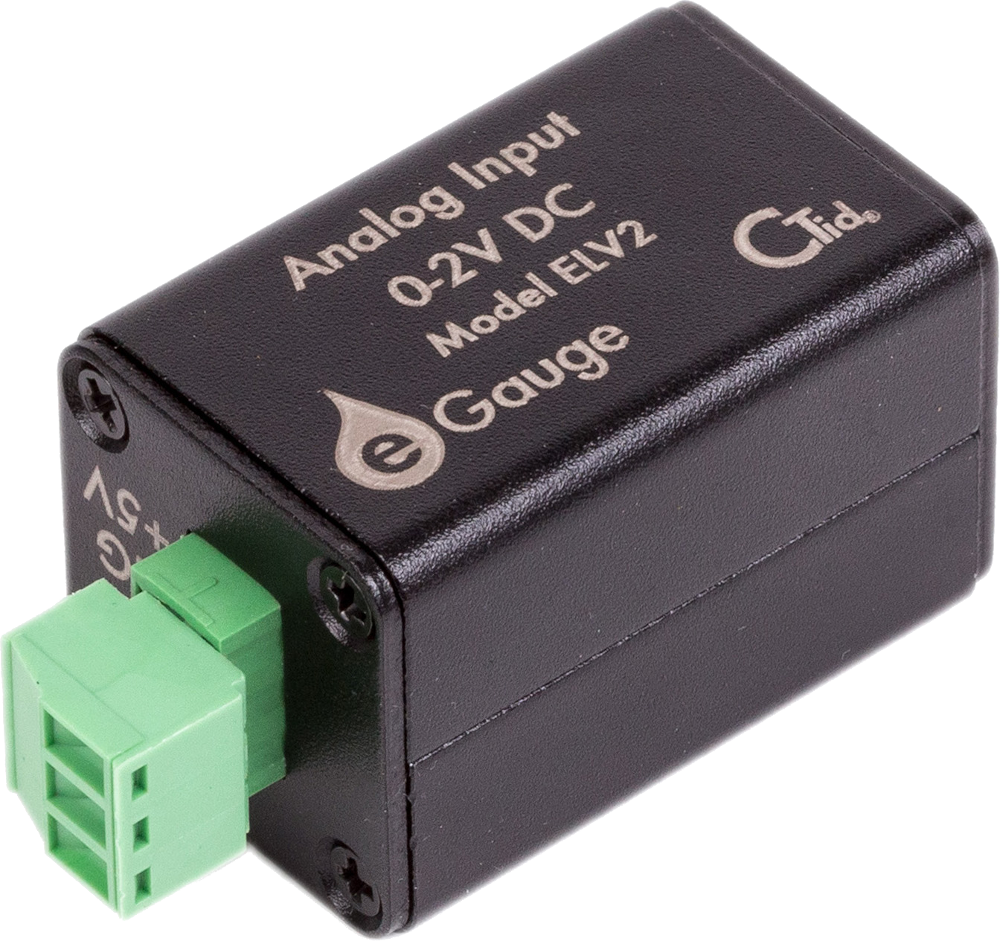](https://kb.egauge.net/uploads/images/gallery/2020-02/2v-sensor-1000x941-transparent.png) | [](https://kb.egauge.net/uploads/images/gallery/2020-02/pulse-topdown.png) | [](https://kb.egauge.net/uploads/images/gallery/2020-02/sensor-rj11.png) |
| *Side view of ELV2* | *Front view of ELV2 with connections* | *Back-side of ELV2 with RJ-11 port and CTid locator LED* |
Requires the [**eGauge Sensor Hub**](https://kb.egauge.net/books/egauge-hardware-product-pages/page/sensor-hub-%28esh044%29 "eGauge Sensor Hub") and eGauge model EG4xxx (Pro or Core), not compatible with older model units.
When monitoring input/output temperatures, it is best to purchase multiple probes in the same order for highest accuracy.
Only use straight-through RJ-11 cables to connect powered sensors to the Sensor Hub. Telephone systems generally use "reverse" style RJ-11 cables which are incompatible with the Sensor Hub. See **[this article](https://kb.egauge.net/books/egauge-installation/page/rj-11-wiring-between-sensor-hub-and-sensors)** for more information on verifying the correct RJ-11 wiring. Every Sensor Hub compatible sensor sold by eGauge Systems comes with a straight-through RJ-11 cable.
The eGauge Temperature Probe Sensor is used in conjunction with the [Sensor Hub](https://kb.egauge.net/books/sensors/page/sensor-hub-%28esh044%29) and an EG4xxx model meter (Core or Pro) to to log temperature data. The Temperature Probe Sensor is used for precision fluid temperature measurement (through thermowell) and precision ambient temperature measurement from 0 °C to 100 °C. For ambient temperature monitoring, see the [Ambient Temperature Sensor (ETLW)](https://kb.egauge.net/books/sensors/page/ambient-temp-sensor-%28etlw%29 "Ambient Temp Sensor (ETLW)"). [See our Sensors product introduction video here](https://www.youtube.com/watch?v=6D82guIQP50&feature=youtu.be).| [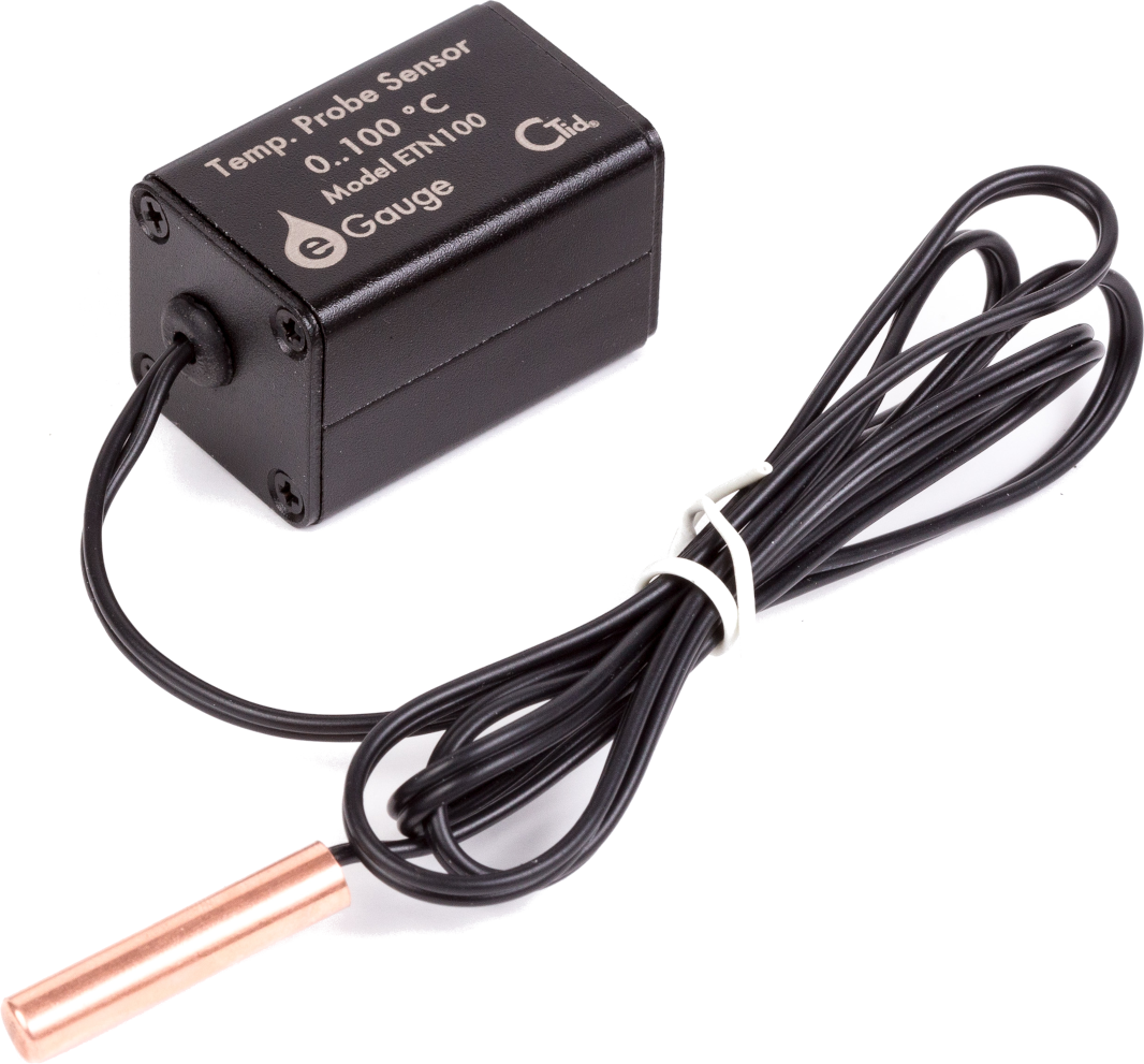](https://kb.egauge.net/uploads/images/gallery/2020-02/probe-temp-sensor-withprobe-1066x991-transparent.png) | [](https://kb.egauge.net/uploads/images/gallery/2020-02/sensor-rj11.png) |
| *Side view of ETN100 and probe* | *Back-side of ETN100 with RJ-11 port and CTid locator LED* |
Requires the [**eGauge Sensor Hub**](https://kb.egauge.net/books/egauge-hardware-product-pages/page/sensor-hub-%28esh044%29 "eGauge Sensor Hub") and eGauge model EG4xxx (Pro or Core), not compatible with older model units.
Only use straight-through RJ-11 cables to connect powered sensors to the Sensor Hub. Telephone systems generally use "reverse" style RJ-11 cables which are incompatible with the Sensor Hub. See **[this article](https://kb.egauge.net/books/egauge-installation/page/rj-11-wiring-between-sensor-hub-and-sensors)** for more information on verifying the correct RJ-11 wiring. Every Sensor Hub compatible sensor sold by eGauge Systems comes with a straight-through RJ-11 cable.
The eGauge Ambient Temperature Sensor (ETLW) is used in conjunction with the [Sensor Hub](https://kb.egauge.net/books/sensors/page/sensor-hub-%28esh044%29) and an EG4xxx model meter (Core or Pro) to record temperature data from systems such as HVAC systems, cold storage, data centers and other controlled environments. For fluid temperature monitoring, see the [Temperature Probe Sensor (ETN100)](https://kb.egauge.net/books/sensors/page/temperature-probe-sensor-%28etn100%29 "Temperature Probe Sensor (ETN100)"). [See our Sensors product introduction video here](https://www.youtube.com/watch?v=6D82guIQP50&feature=youtu.be).| [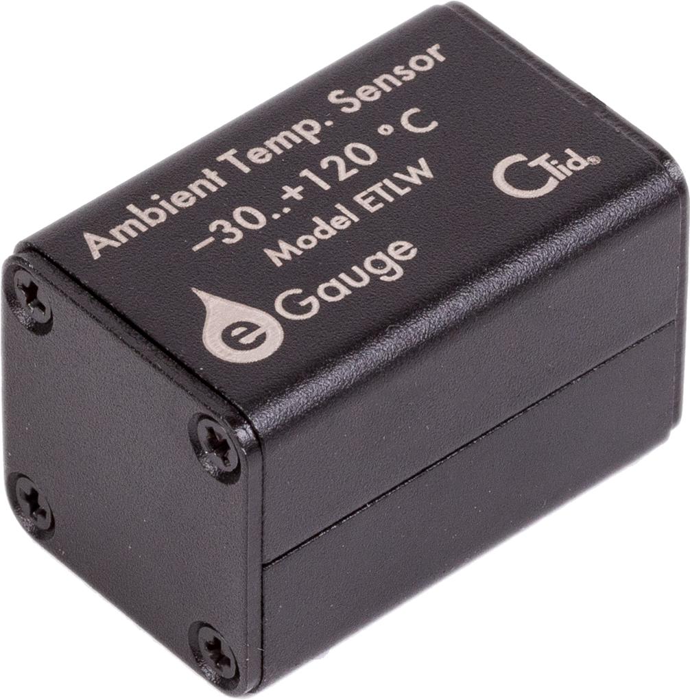](https://kb.egauge.net/uploads/images/gallery/2020-02/image-1582305297233.png) | [](https://kb.egauge.net/uploads/images/gallery/2020-02/sensor-rj11.png) |
| *Side view of ETLW* | *Back-side of ETLW with RJ-11 port and CTid locator LED* |
If using multiple IMT weather stations on the same serial bus, the Modbus address must be changed. See the manufacturer's information at [https://www.imt-solar.com/downloads/](https://www.imt-solar.com/downloads/) under "Software Si-Series" for more information.
If splicing into a "wall wart" style DC power supply wires, verify the polarity of the DC output is correct with a voltmeter. Typically, **the wire with a white stripe or dash** is the **positive** line.
### OEM Data Sheets Visit [https://www.imt-solar.com/](https://www.imt-solar.com/) . Additional or newer version documents may be found in the "Downloads" section. - [Irradiance Sensor Main Unit Reference Guide (required for accessories)](https://www.imt-solar.com/fileadmin/docs/en/products/Si_Instruction-digital_202205_EN.pdf) - [Irradiance Sensor Main Unit Data Sheet](https://www.imt-solar.com/fileadmin/docs/en/products/Si-Sensor_202205_E.pdf) - [Wind Speed Sensor Data Sheet](https://www.imt-solar.com/fileadmin/docs/en/products/Vwind-Si_E.pdf) - [Ambient Temperature Sensor Data Sheet](http://www.imt-solar.com/fileadmin/docs/en/products/Tamb-Si_E.pdf) ### Hardware Included - IMT Weather Station (Si-RS485TC-2T-v-MB) - Barrel connector to screw terminal block set - 12Vdc power supply (120V American outlet wall-wart style) ### Installation and Wiring For best results, the IMT sensor must be installed in the same plane as the solar array. The sensor window should be clean and clear of any obstructions. Follow the mounting instructions included with the IMT sensor, and [contact IMT directly](https://imtsolar.com/contact/) with any questions regarding unique installation environments. The IMT sensor has four wires and a heavier gauge wire shield connector. Depending on the application, the wire shield may or may not be used, and it is not shown in the following diagrams. If required, the wire shield should be connected to **earth ground**, not the RS485 ground or signal ground. Note that proper wiring is *essential*. Failure to wire the IMT sensor correctly will prevent the sensor from functioning and may cause damage. --- ##### Wiring for EG4xxx with RS485-USB adapter The following diagram shows the IMT sensor connected to a 12Vdc power supply and RS485-USB adapter. The eGauge is not shown.If splicing into a "wall wart" style DC power supply wires, verify the polarity of the DC output is correct with a voltmeter. Typically, **the wire with a white stripe or dash** is the **positive** line.
[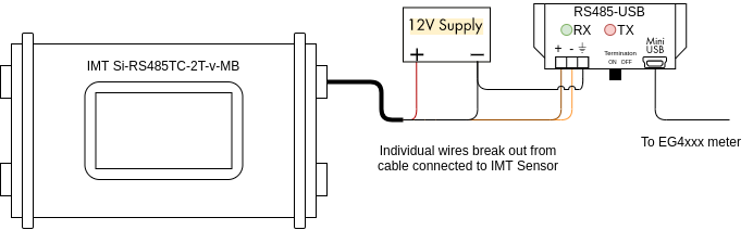](https://kb.egauge.net/uploads/images/gallery/2021-04/image-1619628467279.png) The wire assignments are as follows: Black: Negative side of 12Vdc power supply Red: Positive side of 12Vdc power supply Orange: D- terminal on RS485-USB adapter Brown: D+ terminal on RS485-USB adapterThe larger, thick black wire is a grounded shield and must not be connected to the eGauge, power supply or USB485 converter. Only connect this wire if you know what you are doing as improper grounding conditions can cause damage or communication issues.
Additionally, it is necessary to connect the ground (⏚) terminal on the RS485-USB adapter to the negative terminal of the 12Vdc power supply. A barrel connector with terminal blocks is included with the IMT sensor. Use the female side to quickly connect the IMT sensor to the 12Vdc power supply without splicing any wires. The male side can be discarded or saved for use in another project. [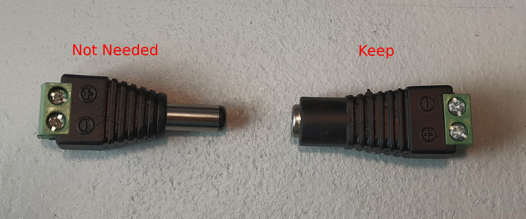](https://kb.egauge.net/uploads/images/gallery/2021-04/image-1619628932764.png) Use the included USB cable to connect the RS485-USB adapter to the eGauge, and make a note of which port is used (USB1 or USB2). Also ensure the termination switch on the RS485-USB adapter is set to "ON". --- ##### Wiring for EG30xx using BF430 serial to Ethernet adapter The following diagram shows the IMT sensor connected to a BF430 serial to Ethernet adapter. The eGauge is not shown. [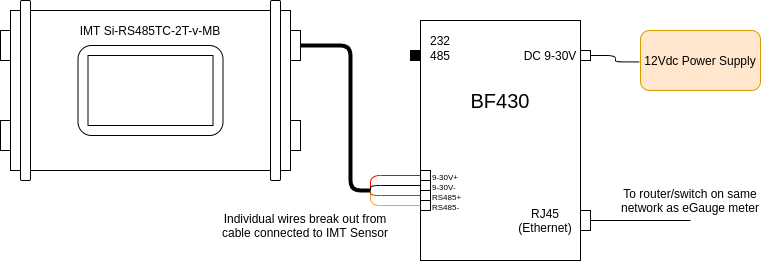](https://kb.egauge.net/uploads/images/gallery/2021-04/image-1619630594867.png) The wire assignments are as follows: Black: 9-30V- Red: 9-30V+ Orange: RS485- terminal on BF430 adapter Brown: RS485+ terminal on BF430 adapter A note on power: The BF430 obtains power through a 9-30Vdc power supply, and can optionally share that power source with a connected device. As such, all four wires on the IMT sensor are connected to the BF430. However, note that the 12Vdc power supply provided by eGauge (or a similar 12Vdc power supply) should be used, as 9Vdc is too low for the IMT sensor. A barrel connector with terminal blocks is included with the IMT sensor, but it is not needed for this application. Discard this piece, or save it for another project. [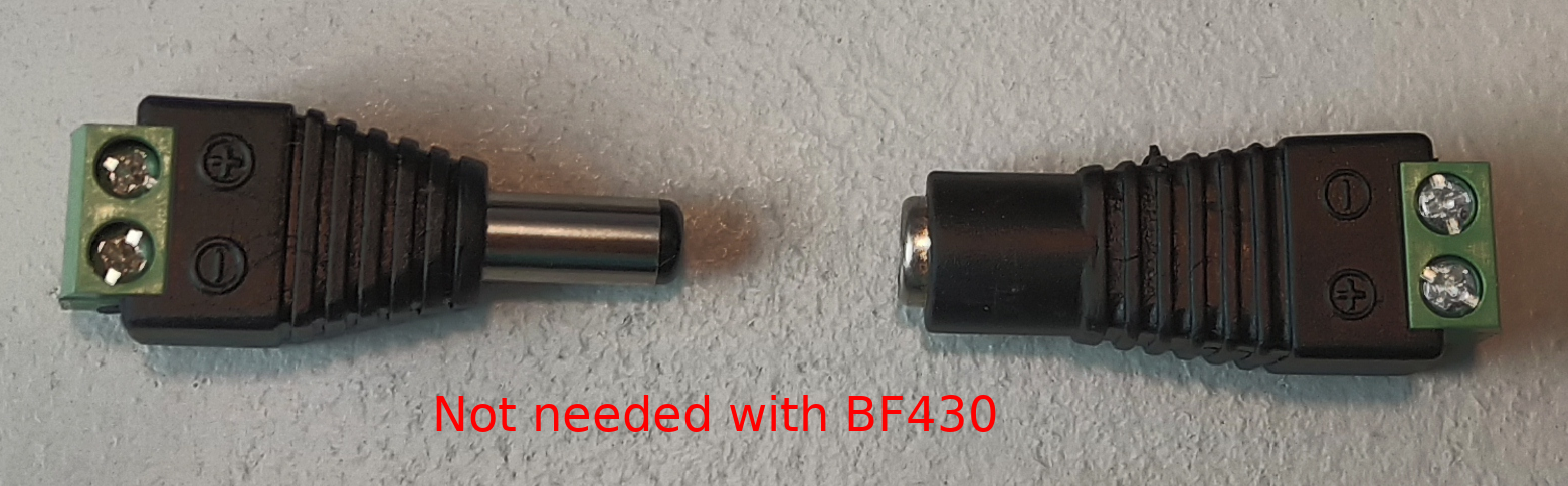](https://kb.egauge.net/uploads/images/gallery/2021-04/image-1619630478825.png) Connect the BF430 to the same local area network as the eGauge, and ensure the external switch is set to "485". --- ### Configuration As a supported device, the IMT sensor has a predefined map built into the eGauge meter. This makes addressing and configuration very simple when using a RS485-USB adapter. Configuration with a BF430 is significantly more complex.Valid credentials are required for the eGauge meter in order to make changes. See [this article](https://kb.egauge.net/books/configuration/page/what-password-do-i-use-to-save-a-change-to-the-settings) for more information.
##### Configuration for EG4xxx using RS485-USB adapter The RS485-USB adapter does not require any configuration on the adapter side. However, it's important to note which USB port is in use by the adapter. It's also necessary to ensure the termination switch is set to "on" when used with the IMT sensor. 1\. Navigate to **Settings -> Installation**. 2\. Under the "Remote Devices" section, click "Add Device" to add a new remote device. 3\. Enter a suitable device name. This field is arbitrary, but should make sense to the end user. 4\. Click the "Edit" button, and set the protocol to "Serial" 5\. Enter the device address. This will be `modbus://imt_si.1@USBX` where X is the USB port (1 or 2). [](https://kb.egauge.net/uploads/images/gallery/2021-04/image-1619631310826.png) 6\. Click the grey "?" next to the device address field. After a few seconds, this should turn into a green check mark. 7\. To save these settings, click the "Save" button at the bottom of the page.If a red X appears instead of a green check mark, ensure the wiring is correct, the USB port is identified correctly, the address is entered correctly, and that the IMT sensor has power.
Assuming a green check mark is displayed, the next step is to configure the eGauge to store data from the IMT sensor. To do this, at least one register will need to be created. 1\. Ensure a green check mark is shown next to the remote device address. If a grey "?" is shown, click it and wait for it to turn into a green check mark. 2\. On the Installation page, navigate to the "Registers" section and click "Add Register". 3\. Enter a suitable register name. This field is arbitrary, but should make sense to the end user. 4\. The default register type will be set to "P". Click the dropdown menu and select the remote device name for the IMT sensor. 5\. A second dropdown menu will appear. Select the remote register to record. [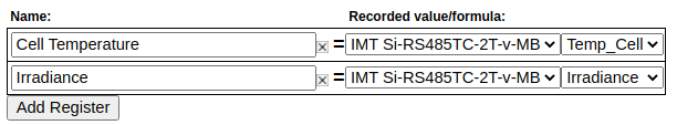](https://kb.egauge.net/uploads/images/gallery/2021-04/image-1619631800730.png) 6\. Repeat steps 2-5 for each remote register. 7\. To save these settings, click the "Save" button at the bottom of the page. The meter will reboot. 8\. Once the meter reboots, the RX and TX LEDs on the RS485-USB adapter should be blinking.The IMT sensor has add-on hardware to measure ambient temperature and windspeed. These registers will be listed even if that hardware is not connected, but they will return invalid values if selected
--- ##### Configuration for EG30xx with BF430 serial to Ethernet adapter The BF430 requires additional configuration through its internal web interface. A computer with an Ethernet port and an Ethernet cable are required for configuration. The two primary areas of concern are applying the correct serial settings (listed below) and setting the BF430 to use either a dynamic IP address (obtained with DHCP) or a static IP address. Refer to the [BF430 manual](https://www.egauge.net/media/support/docs/BF430_manual.pdf) for additional information.Support for the BF430 is limited. Using a RS485 to USB adapter is *strongly* recommended.
1\. Ensure the BF430 is configured to use the following serial settings for RS485 communication: 9600 baud, 8 data bits, no parity, 1 stop bit. 2\. Ensure the BF430 is set to obtain an IP address via DHCP or use an appropriate static IP address depending on the network requirements (generally, DHCP is preferred). Once the BF430 has been configured and wired: 1\. Navigate to **Settings -> Installation**. 2\. Under the "Remote Devices" section, click "Add Deice" to add a new remote device. 3\. Enter a suitable device name. This field is arbitrary, but should make sense to the end user. 4\. Click the "Edit" button, and set the protocol to "Serial" 5\. Enter the device address. This will be `modbus://imt_si.1@MAC` where MAC is the MAC address of the BF430. If the BF-430 has been configured with a *static IP*, the IP may be used instead. [](https://kb.egauge.net/uploads/images/gallery/2021-04/image-1619639722258.png) 6\. Click the grey "?" next to the device address field. After a few seconds, this should turn into a green check mark. 7\. To save these settings, click the "Save" button at the bottom of the page.If a red X appears instead of a green check mark, ensure the wiring is correct, the USB port is identified correctly, the address is entered correctly, and that the IMT sensor has power.
Assuming a green check mark is displayed, the next step is to configure the eGauge to store data from the IMT sensor. To do this, at least one register will need to be created. 1\. Ensure a green check mark is shown next to the remote device address. If a grey "?" is shown, click it and wait for it to turn into a green check mark. 2\. On the Installation page, navigate to the "Registers" section and click "Add Register". 3\. Enter a suitable register name. This field is arbitrary, but should make sense to the end user. 4\. The default register type will be set to "P". Click the dropdown menu and select the remote device name for the IMT sensor. 5\. A second dropdown menu will appear. Select the remote register to record. [](https://kb.egauge.net/uploads/images/gallery/2021-04/image-1619631800730.png) 6\. Repeat steps 2-5 for each remote register. 7\. To save these settings, click the "Save" button at the bottom of the page. The meter will reboot. 8\. Once the meter reboots, the RX and TX LEDs on the BF430 adapter should be blinking. --- ### Viewing Data The data recorded from the IMT sensor can be viewed like any other data point recorded by the meter. To see this data, navigate to the main graph page and select the appropriate register(s) from the list under the main graph. In the following example, the graph is set to display irradiance data (with temperature and windspeed data as options under the main graph. [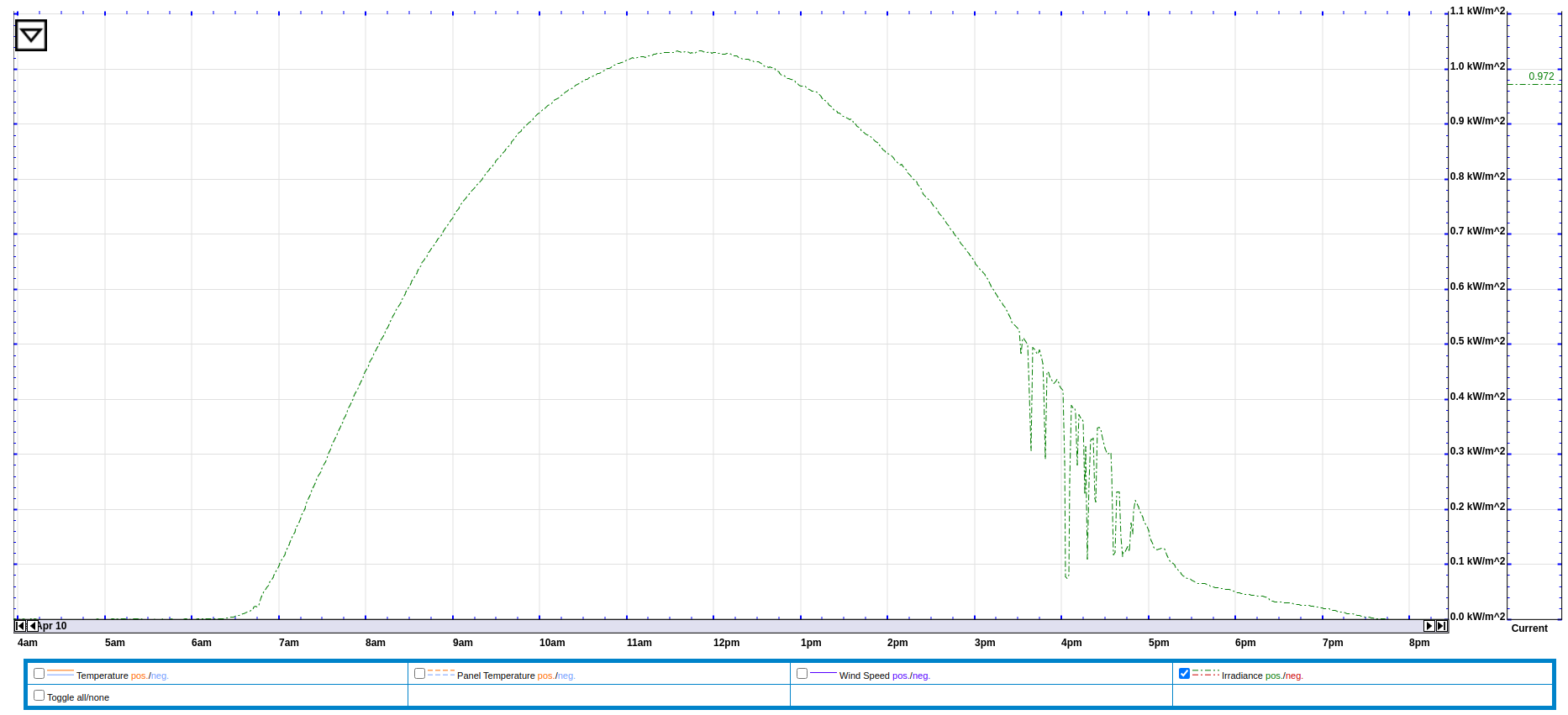](https://kb.egauge.net/uploads/images/gallery/2021-04/image-1619712737118.png) Data from the IMT sensor can also be used in formula registers to calculate the estimated solar production at a site. The formula for this calculation requires real time irradiance and temperature data (obtained from the IMT sensor), the array's rating in watts, and the panel temperature coefficient (usually a small negative number). The following example shows this formula based on a 10kW array and a temperature coefficient of -.12%. [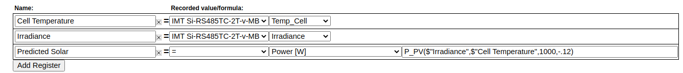](https://kb.egauge.net/uploads/images/gallery/2021-04/image-1619640250900.png) The formula field contains: `P_PV($"Irradiance",$"Cell Temperature",10000,-.12)` --- ### Additional Sensors The IMT sensor supports two additional sensors: a wind speed sensor and an ambient temperature sensor. These sensors connect directly to the IMT sensor body. To connect these sensors, remove the appropriate threaded cap from the sensor body (the wind speed sensor uses the two pin connector, and the ambient temperature sensor uses the three pin connector). In the image below, one cap has been removed (left). [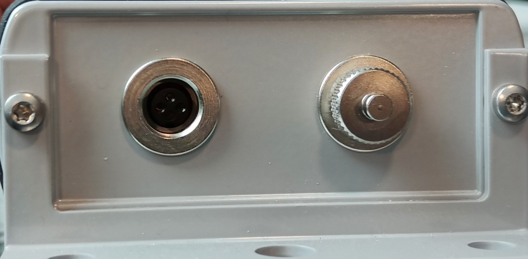](https://kb.egauge.net/uploads/images/gallery/2021-04/image-1619640582003.jpg) When using an add-on sensor, the configuration is exactly the same *except* additional registers will need to be created to record data from the add-on sensors.Do not connect anything besides official IMT add-on sensors to these ports. Doing so will cause damage and void the warranty on the IMT sensor.
--- ### Suggested Reading - [RS485-USB adapter](https://kb.egauge.net/books/egauge-hardware-product-pages/page/egauge-usb-serial-converter-%28usb485%29) - [General information on connecting remote devices via RS485-USB adapter](https://kb.egauge.net/books/egauge-meter-communication/page/remote-device-via-egauge-usb485-adapter) - [RS485-Ethernet adapter (BF430)](https://kb.egauge.net/books/egauge-hardware-product-pages/page/rs485-to-ethernet-converter-%28bf430%29) - [Remote devices and third party devices](https://kb.egauge.net/books/egauge-meter-configuration/page/remote-devices-and-third-party-devices) # Sensor Hub (ESH044) ##### [ Visit the online store page](https://store.egauge.net/sensor-hub "Visit the online store now!") ##### Model: ESH044For use with [**supported eGauge sensors**.](https://kb.egauge.net/books/egauge-hardware-product-pages/chapter/environmental-analog-and-other-sensors)
Only use straight-through RJ-11 cables to connect powered sensors to the Sensor Hub. Telephone systems generally use "reverse" style RJ-11 cables which are incompatible with the Sensor Hub. See **[this article](https://kb.egauge.net/books/egauge-installation/page/rj-11-wiring-between-sensor-hub-and-sensors)** for more information on verifying the correct RJ-11 wiring. Every Sensor Hub compatible sensor sold by eGauge Systems comes with a straight-through RJ-11 cable.
The eGauge Sensor Hub can connect up to four sensors to EG4xxx meter inputs. Any combination of powered and non-powered sensors can be used. Switches select whether the powered or non-powered port is connected to the meter. The RJ-45 breakout cable is used to connect the Sensor Hub to up to four neighboring inputs on the meter. The RJ45 coupler can be used to extend the length of the RJ45 cable as needed. Multiple Sensor Hubs can be used to connect more than four sensors to a meter. For current transformers (CTs), the Sensor Hub provides a convenient method to extend CT cable length without requiring splicing or modifying the CT leads.For current transformers (CTs) total **combined** distance for the RJ45 cable and CT leads must not exceed 100'/33m.
For [powered sensors](https://kb.egauge.net/books/egauge-hardware-product-pages/chapter/environmental-analog-and-other-sensors "Environmental, Analog and Other Sensors"), the Sensor Hub provides a convenient method to adapt from the sensor's RJ11 cable to the 2-pin terminal plug of the EG4xxx meter. The 5V supply required for these sensors can be provided via mini-USB cable or 2-pin terminal plug.For powered sensors total **combined** distance for the RJ45 cable and CT leads must not exceed 1650'/500m.
[See our Sensors product introduction video here](https://www.youtube.com/watch?v=6D82guIQP50&feature=youtu.be).| [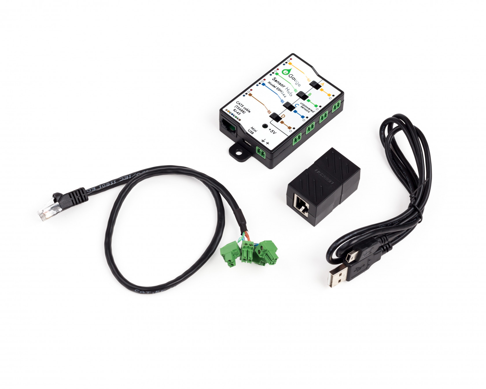](https://kb.egauge.net/uploads/images/gallery/2020-06/sensor-hub-kit.jpg) *eGauge Sensor Hub (ESH044)* |
Only input +5Vdc to the power terminal (if not using USB) when using powered sensors (RJ-11 connections). Other voltages will cause damage.
- The switch must be in the correct position (left for RJ11 connected sensors, right for 2-pin sensors) - Lines adjacent to the to the inputs have colors that match the 2-pin breakout cable color pairs - If extending CTs, do not install the Sensor Hub inside a distribution or breaker panel, only the CTs should be inside. 1. Connect the sensor to one of the 4 ports on the Sensor Hub. If using CTid powered sensors such as the ETN100 (temperature probe), ETLW (ambient temperature), EPS (pulse), ELV2 (2V analog / dry contact), or EV1000 (high voltage sensor) the sensors connect via RJ11 on the left-side of the Sensor Hub. If extending CTs, the 2-pin plug on the CT lead connect to the 2-pin sockets on the right-side of the Sensor Hub. A combination of CTs and powered sensors may be used. Only a single powered or unpowered sensor may be used on each port (yellow/A, green/B, blue/D, and brown/D). 2. Set each switch to the side the sensor is connected. If a powered sensor is connected to the port adjacent to the yellow line, the adjacent switch should be in the left position. 3. If using powered sensors, the Sensor Hub must be powered by 5V DC. This can be either via Mini-USB or the 2-pin plug to the right of the USB port. Using any voltage except 5V DC will cause damage to attached sensors and possibly the eGauge meter. If only using for CT extensions, **do not** power the Sensor Hub. The LED will turn green when there is power applied. 4. If the distance from the Sensor Hub to the eGauge is ~1 foot or less, connect the included RJ45 to 2-pin breakout cable to the RJ45 port to the left of the USB on the Sensor Hub. If there will be distance between the eGauge meter and Sensor Hub 1. Run a standard CAT5 Ethernet cable between the eGauge and Sensor Hub location. 2. Connect one end of the Ethernet cable to the Sensor Hub RJ45 plug. 3. On the other end, attach the RJ45 coupler (included with the Sensor Hub) to the Ethernet line, then connect the Ethernet to 2-pin breakout cable to the other side of the RJ45 coupler. 5. Connect the 2-pin plugs of the breakout cable to the eGauge sensor ports. The color of the twisted pair wires on the breakout cable match with the colored lines on the Sensor Hub to identify which sensors they are for. See images below. 6. If using a CTid sensor that reads external signals, such as the EC420 or EPS, connect the output of the sensor to the CTid sensor connected to the Sensor Hub. Not all sensors utilize all inputs. Refer to the Assembly/installation information information in the sensor's [product page](https://kb.egauge.net/books/egauge-hardware-product-pages) in the support library for specific information. 7. Finally, [configure the sensors](https://kb.egauge.net/books/sensors/page/configuring-ctid-enabled-sensors) that were connected. ### 2-bin breakout cable colors 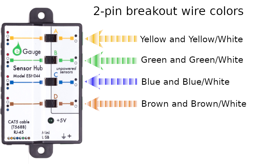| [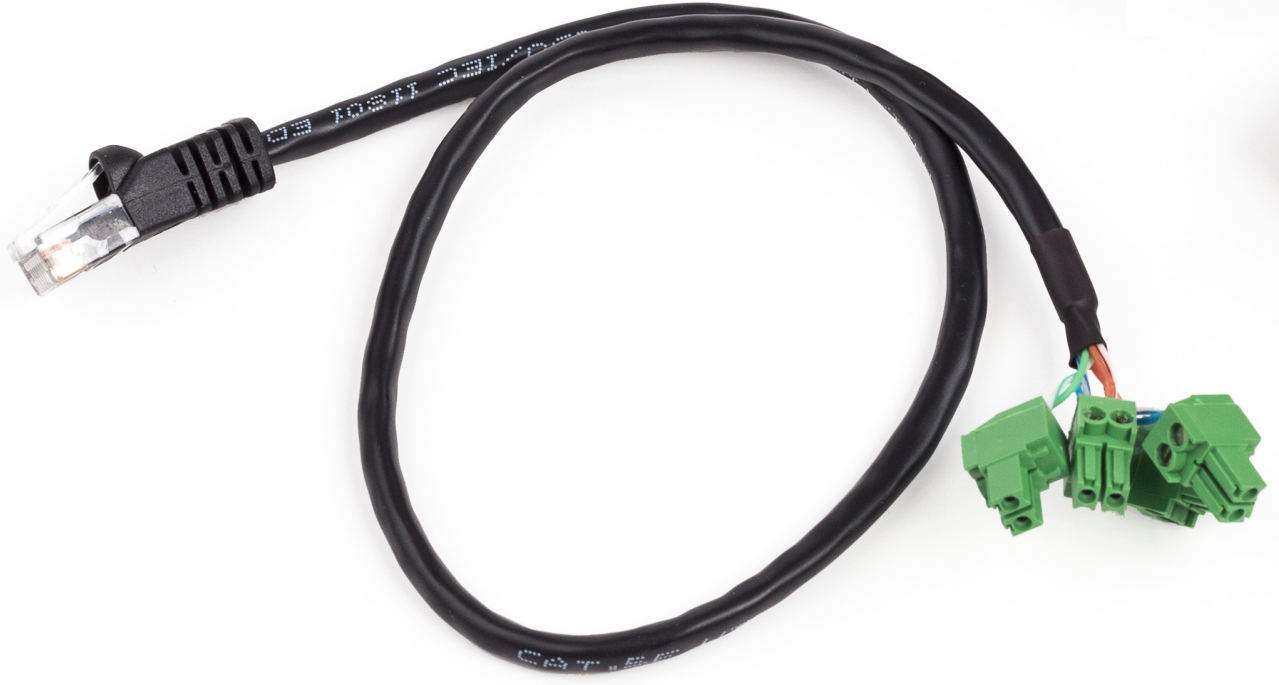](https://kb.egauge.net/uploads/images/gallery/2020-02/breakout-cable.png) |
| *RJ-45* to 2-pin breakout cable. Each 2-pin plug uses either green+green/white, blue+blue/white, brown+brown/white, or yellow+yellow/white. |
Requires the [**eGauge Sensor Hub**](https://kb.egauge.net/books/egauge-hardware-product-pages/page/sensor-hub-%28esh044%29 "eGauge Sensor Hub") and eGauge model EG4xxx (Pro or Core), not compatible with older model units.
Only use straight-through RJ-11 cables to connect powered sensors to the Sensor Hub. Telephone systems generally use "reverse" style RJ-11 cables which are incompatible with the Sensor Hub. See **[this article](https://kb.egauge.net/books/egauge-installation/page/rj-11-wiring-between-sensor-hub-and-sensors)** for more information on verifying the correct RJ-11 wiring. Every Sensor Hub compatible sensor sold by eGauge Systems comes with a straight-through RJ-11 cable.
The eGauge High Voltage sensor is used in conjunction with the [Sensor Hub](https://kb.egauge.net/books/sensors/page/sensor-hub-%28esh044%29) and an EG4xxx model meter (Core or Pro) which allows EG4xxx meters to read voltages up to 1,000 VDC or 707 VAC.| [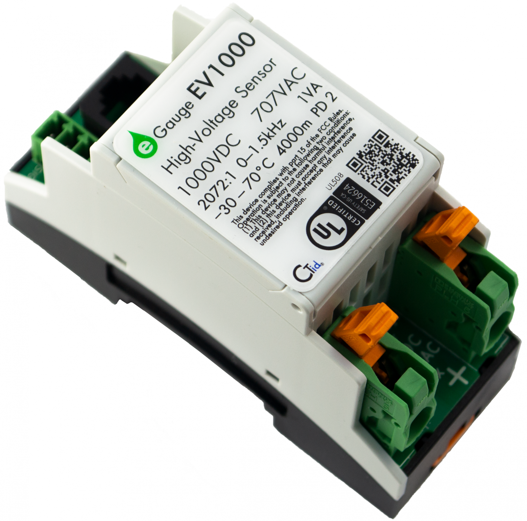](https://kb.egauge.net/uploads/images/gallery/2021-02/main.png) |
| *eGauge EV1000 High Voltage Sensor* |
The high voltage inputs to the EV1000 can be connected Line-to-Line or Line-to-Neutral as long as the voltage potential does not exceed 1,000 VDC or 707 VAC. Safety grounds cannot be used for voltage measurements.
#### Connection to EG4xxx Meter 1. It is not advisable to extend the RJ11 leads from the Sensor to Sensor Hub. It is acceptable to use a longer RJ45 cable from the *Sensor Hub* to the *eGauge*. 2. If RJ11 cable between *Sensor* and *Sensor Hub* must be extended, it is advisable to use twisted pair wires, such as a CAT5 cable with RJ11 plugs (most commonly used for DSL modems). 3. If terminating own cables, both RJ11 and RJ45 cables should be straight-through cables, with the same color order on both ends. 4. See Installation Examples for common use cases of the EV1000. 1. [Install the sensors and Sensor Hub](https://kb.egauge.net/link/174#bkmrk-assembly%2Finstallatio). 2. Connect the EV1000 to a voltage reference no greater than 1000Vdc or 707Vac. 3. [Configure the sensors](https://kb.egauge.net/books/sensors/page/configuring-ctid-enabled-sensors). #### Connection to non-eGauge meter inputs Use the 4-pin connector next to the RJ11 port. +5 VDC and ground is required to power the sensor. SIG+ and SIG- output a ±5V signal proportional to the line inputs. ## Documents - [Manual](https://www.egauge.net/media/support/docs/ev1000-manual.pdf) - [Spec Sheet](https://www.egauge.net/media/support/docs/WEB-EV1000-datasheet.pdf) - [FCC Declaration](https://www.egauge.net/media/support/docs/ev1000-fcc-declaration-of-conformity.pdf) ## Installation Examples - [480V or 600V Delta Service](https://kb.egauge.net/books/egauge-installation/page/monitoring-480v-and-600v-delta-systems) - [347/600V Service](https://kb.egauge.net/books/egauge-installation/page/monitoring-347600v-services) - [Multiple Services](https://kb.egauge.net/books/egauge-installation/page/monitoring-multiple-services-with-one-egauge-meter) ## Related Information - [Sensor Hub Product Page](https://kb.egauge.net/books/egauge-hardware-product-pages/page/sensor-hub-%28esh044%29) - [Configuring CTid Sensors](https://kb.egauge.net/books/egauge-meter-configuration/page/configuring-ctid-enabled-sensors) - [Monitoring 347/600V Wye Services](https://kb.egauge.net/books/advanced-egauge-operation/page/monitoring-347600v-services) ### # 4-20mA Sensor (EC420) ##### [ Visit the online store page](https://store.egauge.net/EC420-current-sensor "Visit the online store now!") ##### Model: EC420Requires the [**eGauge Sensor Hub**](https://kb.egauge.net/books/egauge-hardware-product-pages/page/sensor-hub-%28esh044%29 "eGauge Sensor Hub") and eGauge model EG4xxx (Pro or Core), not compatible with older model units.
Only use straight-through RJ-11 cables to connect powered sensors to the Sensor Hub. Telephone systems generally use "reverse" style RJ-11 cables which are incompatible with the Sensor Hub. See **[this article](https://kb.egauge.net/books/egauge-installation/page/rj-11-wiring-between-sensor-hub-and-sensors)** for more information on verifying the correct RJ-11 wiring. Every Sensor Hub compatible sensor sold by eGauge Systems comes with a straight-through RJ-11 cable.
The eGauge 4-20mA Sensor is used in conjunction with the [Sensor Hub](https://kb.egauge.net/books/sensors/page/sensor-hub-%28esh044%29) and an EG4xxx model meter (Core or Pro) to read a 4-20mA current loop sensor such as pressure sensors, water level sensors, temperature probes, and other industrial sensors that output a 4-20mA current loop. [See our Sensors product introduction video here](https://www.youtube.com/watch?v=6D82guIQP50&feature=youtu.be).| [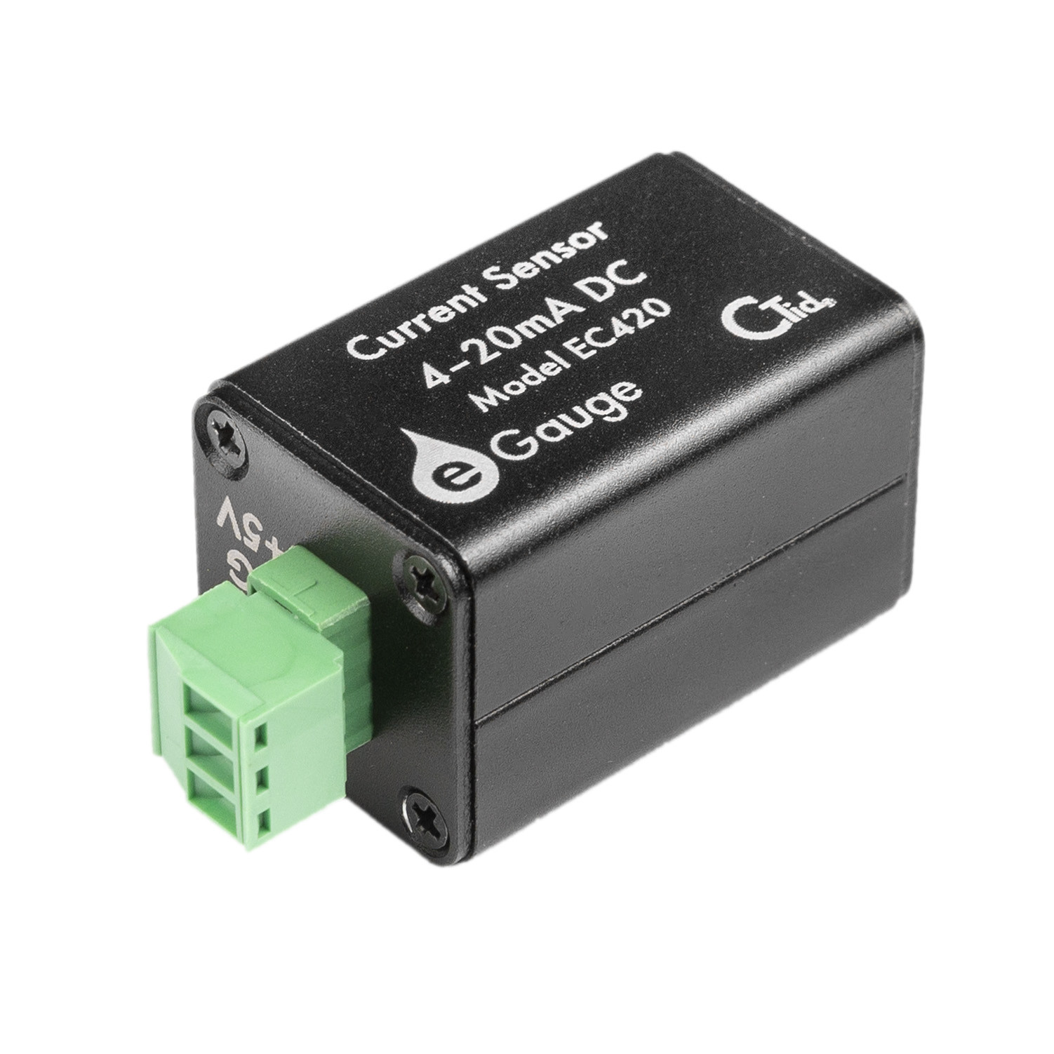](https://kb.egauge.net/uploads/images/gallery/2021-08/image-1628193345184.jpg) |
| *eGauge EC420 4-20mA Sensor* |
A compatible T-Mobile dataplan can be purchased through eGauge Systems. eGauge cannot guarantee support for dataplans from other parties. eGauge supplied data plans are for use with eGauge meters and not third party products, line suspension or termination will occur if there is excessive data usage from third-party devices or general internet usage.
Modems sold by eGauge systems are pre-configured for the T-Mobile service provided by eGauge and utilize InHand Networks device manager for remote troubleshooting and customer assistance.
Metered (not unlimited) data plans can accrue charges for data overages. eGauge recommends against using metered data plans without extensive testing for data usage. Data usage is not fully predictable and will greatly vary with interface access. See **[this article](https://kb.egauge.net/books/connectivity/page/how-much-data-%28bandwidth%29-does-the-egauge-use)** for additional information on data usage.
If installing in an underground or high electrical noise area, a custom antenna solution or separate mounting location for the cellular modem may be necessary in order to have sufficient cellular signal.
| [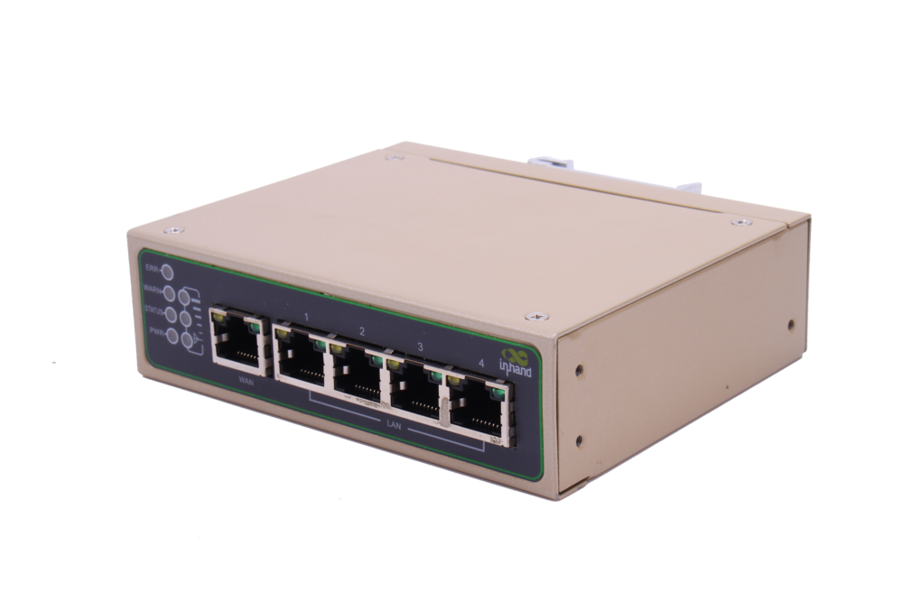](https://kb.egauge.net/uploads/images/gallery/2021-04/ir615.png) |
| ***Inhand Networks IR615*** |
The cellular antennas must be located on the outside of any enclosure. Even plastic enclosures can degrade or block a cellular signal.
1. If the modem is ordered with a data plan, an activation instruction sheet will be included with a SIM card. Insert the SIM card into the modem as shown above, **if there are multiple SIM card slots, use the one labeled "SIM 1"**. Follow the data plan activation instructions provided to activate the data plan. 2. Locate a suitable location to install the cell modem. If installing in a Powered Enclosure Kit (PEK), mount on the DIN rail. 3. If using the PEK or other suitable enclosure, use the 2x short SMA extension cables to connect from the ANT and AUX connectors on the modem to create a bulkhead connector on the enclosure. 4. Connect the antennas to the bulkhead connectors on the enclosure, or directly to the cell modem if not using an enclosure. 5. Connect the power cord to the cellular modem. 6. Connect the eGauge meter via Ethernet to a LAN port on the modem. ## Software configuration and troubleshootingModems provided by eGauge are pre-configured to work on the T-Mobile network using data plans provided by eGauge Systems.
The APN for plans provided by eGauge with the IR615 modem is `iot.tmowholesale` and is automatically set in the configuration files provided below.
If the modem is not functioning and configuration may have been modified after shipment, perform a factory reset and upload the eGauge-specific cellular configuration if using a dataplan provided by eGauge Systems. ### LED indicator description The modem has 3 signal LEDs to indicate signal strength: 1 LEDs: Signal strength 1-9 (Signal strength is weak, please check antenna and the signal strength of current location). 2 LEDs: Signal strength 10-19 (signal strength is adequate, and the modem can be used). 3 LEDs: Signal strength 20-31 (signal strong). The other LED behavior is described below: [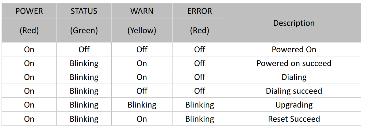](https://kb.egauge.net/uploads/images/gallery/2020-11/image-1605818316027.png) ### Factory Reset 1. Power on the modem and allow it at least 60 seconds to fully start running. Locate the Reset button below the antenna connections and find a paperclip or pin to push the button. [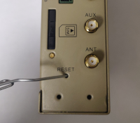](https://kb.egauge.net/uploads/images/gallery/2020-11/image-1605818815944.png) 2. Use a push-pin or paperclip to hold down the "Reset" button on the side of the modem until the "STATUS" LED starts flashing and the "ERROR" LED remains solid, then release the button. 3. When the button is released, the "ERROR" LED will turn off. Within 30 seconds, press and hold the "RESET" button again until the "ERROR" LED starts flashing and then release it. 4. The unit will now restore factory default settings. The STATUS, WARN, and ERROR LEDs will all light up solid during the factory reset process. Allow the unit at least 60 seconds to fully factory reset, and then perform the initial configuration steps below. ### Configuration stepsModems provided by eGauge are pre-configured to work on the T-Mobile network using data plans provided by eGauge Systems.
1. Identify the firmware version on the cell modem. On the bottom of the modem near the label is a sticker that indicates the firmware version. Below shows the modem uses firmware version **2.3.0**.[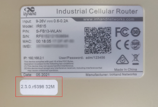](https://kb.egauge.net/uploads/images/gallery/2021-06/image-1624647978591.png) If logged into the modem interface, the firmware version may be found on the main page. This modem shows it runs firmware version **2.4.3**: [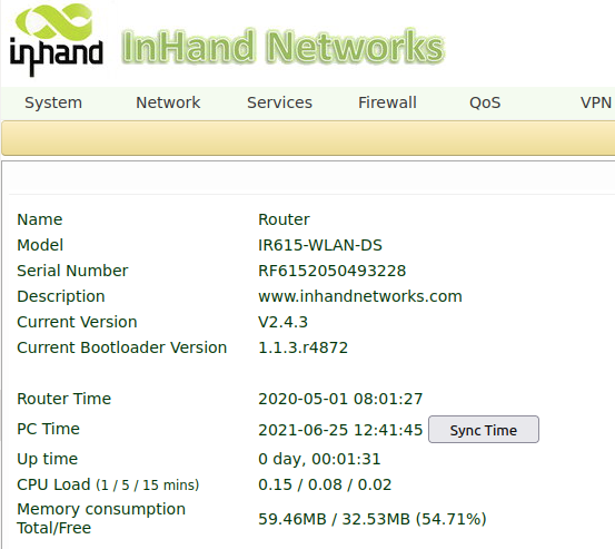](https://kb.egauge.net/uploads/images/gallery/2021-06/image-1624648107190.png) 2. Download the configuration file that corresponds to your firmware version where *x* is any number. This file will be uploaded to the modem in a later step.| 2.3.*x* | [v2.3.x-egauge-ir615-DS-cell-config\_qts.dat](https://kb.egauge.net/attachments/39) |
| 2.4.x | [v2.4.x-egauge-ir615-DS-cell-config.dat](https://kb.egauge.net/attachments/38) |
| **Page location** | **Description** |
| Tools -> Ping | Have the modem ping an external IP or domain. |
| Status -> Modem | Contains signal level, RSSI, SIM card number, network type and other modem-related information |
| Status -> Network Connections | Dialup (cellular) IP information from cellular provider |
| Status -> Device List | DHCP list of connected devices to the LAN ports |
| Status -> Log | Raw log from modem |
The Multitech cellular offering has been replaced by the [Inhand Networks IR615](https://kb.egauge.net/books/egauge-hardware-product-pages/page/cellular-modem-%28inhand-networks-ir615%29) cellular modem starting in November 2020.
- Starting May 2022, cellular plans using the **fast.t-mobile.com** APN must have a new SIM card and new APN configured for continued service. The new APN is **iot.tmowholesale** and requires a new SIM card to be installed. Please follow the **SIM card installation** and **Initial Configuration** instructions in the **[Multitech setup instructions article](https://kb.egauge.net/books/other-hardware-documentation/page/multitech-cell-modem-setup-%28mte-lat6-b07%29)**. - Old SIM cards will not function after May 2022 and can be identified by having a pink T-Mobile logo on it. The new/current SIM cards are white and do not have any branding on them. *Current manufacturer information: Multitech model MTE-LAT6-B07*A compatible T-Mobile dataplan can be purchased through eGauge Systems. eGauge cannot guarantee support for dataplans from other parties.
Metered (not unlimited) data plans can accrue charges for data overages. eGauge recommends against using metered data plans without extensive testing for data usage. Data usage is not fully predictable and will greatly vary with interface access. See **[this article](https://kb.egauge.net/books/connectivity/page/how-much-data-%28bandwidth%29-does-the-egauge-use)** for additional information on data usage.
The Multitech cellular modem is a cellular to Ethernet modem that can provide the eGauge unit with internet access on a 4G LTE T-Mobile or AT&T network.| [](https://kb.egauge.net/uploads/images/gallery/2020-06/multitech-cell-modem.png) |
| *Multitech Cell Modem* |
|  |
| *TP-Link USB powered WiFi adapter* |
| [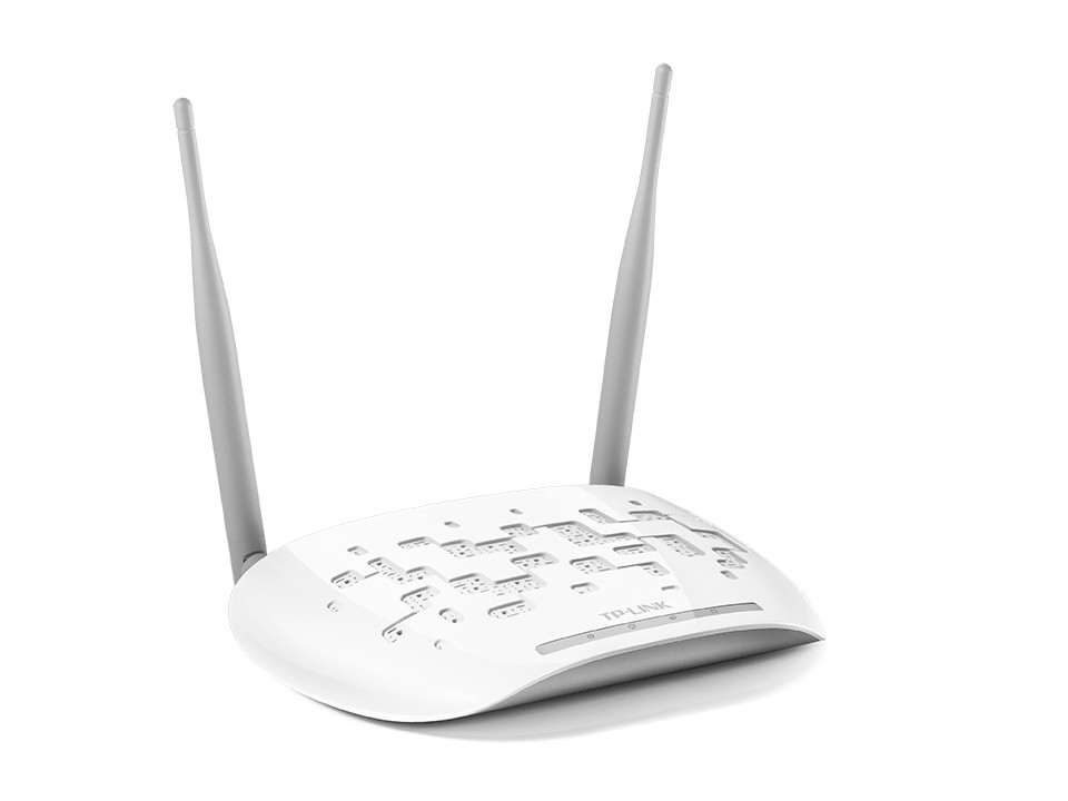](https://kb.egauge.net/uploads/images/gallery/2020-06/tp-link-wifi-ap.jpg) |
| *TP-Link Wifi Access Point* |
This is a discontinued product. eGauge Systems no longer offers HomePlug-compatible devices. If wireless communication is required, please utilize the [WiFi-enabled EG42xx series meter](https://kb.egauge.net/books/egauge-hardware-product-pages/page/meter-egauge-core-and-pro-with-wifi).
The HomePlug AV adapter is used by compatible eGauge models to bring network communication over the existing building power lines. The HomePlug AV adapter plugs directly into a 120V outlet, connects to the router/switch using Ethernet, and allows compatible eGauge models to communicate over the the building's electrical wiring. - HomePlug communication is only recommended for residential use, and is not needed when using an alternative communication method, such as Ethernet direct, cellular, or WiFi. - Ensure HomePlug adapter is powered by same phase as eGauge meter L1 connection and is not more than 100 feet of wiring distance from the eGauge meter. - Do not plug HomePlug adapter into surge protector or UPS. - Do not push or hold the button on the HomePlug adapter without full knowledge of pair/reset process. Pushing the button on the HomePlug adapter may result in communication loss. - The HopmePlug AV is only for EG301x and EG41xx (Pro/Core Residential). eGauge2 models cannot use this HomePlug. Contact eGauge Support if you are unsure what model you have.| [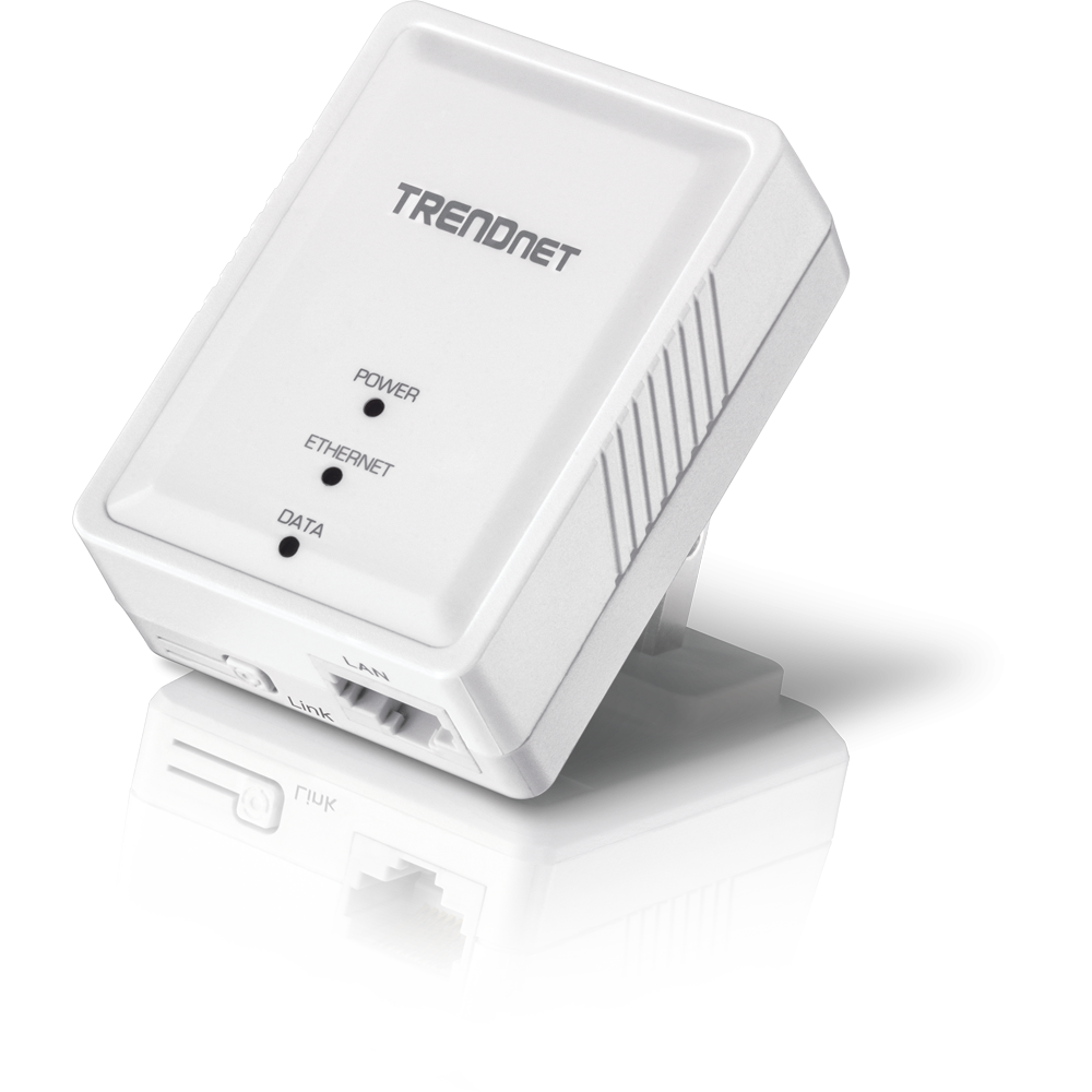](https://kb.egauge.net/uploads/images/gallery/2020-06/trendnet-homeplug-av-tpl-406e.png) |
| *TRENDnet HomePlug AV* |
EG4xxx (Pro and Core) are recommended to utilize the **[eGauge USB485](https://kb.egauge.net/books/egauge-hardware-product-pages/page/egauge-serial-usb-converter-%28usb485%29)** (serial to USB) adapter instead if possible.
Power can be provided (9-30V) to either terminals or barrel jack plug. eGauge sells a **[compatible 12Vdc](https://kb.egauge.net/books/egauge-hardware-product-pages/page/product-page-12-volt-power-supply)** power supply.
The Chiyu BF-430 is an RS-485/RS-232 to Ethernet converter. It is required for serial communication to third-party devices (for example, Modbus RTU) on older eGauge models without USB ports or to communicate over a network rather than serial line directly to the eGauge.| [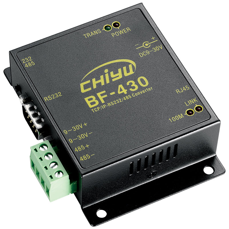](https://kb.egauge.net/uploads/images/gallery/2020-06/chiyu-bf430.jpg) |
| *BF430 Serial-to-Ethernet Converter* |
Do not apply power to both barrel jack and voltage terminals.
Serial settings are configured in software on the BF-430 and must be set correctly through web interface for use.
1. Set the DIP switch in the upper left to 485 (or 232, if using the RS232 terminal connections). 2. Connect the Ethernet (RJ45) to the local network. 3. Connect the 485+ and 485- to the appropriate connections on the remote serial device (or RS232 if used instead). 4. Apply power to the BF-430 using a barrel jack or 9~30V+ and 9~30V- terminals appropriately. ### Software configuration Information [BF-430 Manual](https://www.egauge.net/media/support/docs/BF430_manual.pdf) ## Documents [BF-430 Manual](https://www.egauge.net/media/support/docs/BF430_manual.pdf) ## Related Information - [RS485 to USB converter (USB485)](https://kb.egauge.net/books/egauge-hardware-product-pages/page/product-page-rs485-usb-converter "Product Page: RS485-USB Converter") - [IMT irradiance and weatherstation wiring information](https://kb.egauge.net/books/third-party-hardware-documentation/page/imt-si-rs485tc-2t-v-mb-irradiance-sensor-wiring-diagrams "IMT Si-RS485TC-2T-v-MB irradiance sensor wiring diagrams") - [Reading from any remote Modbus device](https://kb.egauge.net/books/egauge-meter-communication/page/custom-modbus-definitions-%28read-from-any-modbus-device%29 "Custom Modbus definitions (read from any Modbus device)") # eGauge USB-Serial Converter (USB485) ##### [ Visit the online store page](https://store.egauge.net/USB_485 "Visit the online store now!") ##### Model: USB485 The eGauge USB485 is used to receive and send serial data between a RS485 serial chain and a host's USB port. Primarily it is used for compatible eGauge meters (EG4xxx Core and Pro) to record data from remote Modbus devices (such as inverters, temperature sensors, and other meters), or for other systems (such as a building automation system or other data loggers) to read data from the eGauge via Modbus RTU. It may be used for other non-eGauge applications as it utilizes a well known FT230X chipset from FTDI. However, eGauge Systems does not provide support for these applications.| [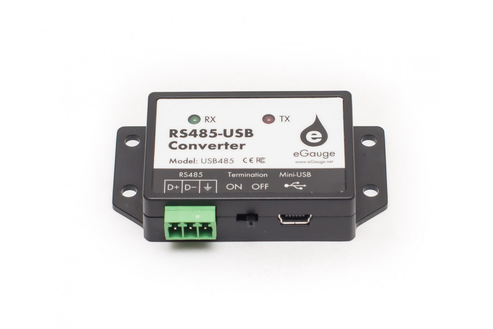](https://kb.egauge.net/uploads/images/gallery/2020-06/usb485.jpg) |
| *eGauge RS485-USB Converter* |
Ensure proper wiring between serial devices. Only connect data signals, and signal ground (not earth ground).
1. Wire the serial line to the D+, D-, and signal ground. Use twisted pair wire for D+ and D- connections. 2. Turn the termination DIP switch to ON if it is the **last** connection on the serial line. Termination should be OFF if it is daisy chained in-between devices. 3. Connect the Mini USB cable to the EG4xxx USB1 or USB2 port. Take note of which port is used. ### Multiple serial devices can be daisy chained on the same line as shown in the diagram below: [](https://s3.amazonaws.com/cdn.freshdesk.com/data/helpdesk/attachments/production/25012072323/original/AqpfSqLc1M0n61_BcyOkobwnb69vKwug5g.png?1562955781) --- ### Software configuration Information - If exporting eGauge data via Modbus RTU to another system, see the [Modbus output communication article here](https://kb.egauge.net/books/egauge-meter-communication/page/modbus-output-communication "Modbus Output Communication"). - If importing data from a remote Modbus RTU device to the eGauge, see the [Modbus input article here](https://kb.egauge.net/books/egauge-meter-communication/page/custom-modbus-definitions-%28read-from-any-modbus-device%29 "Custom Modbus definitions (read from any Modbus device)"). ## Documents - [Datasheet](https://www.egauge.net/media/support/docs/usb485_datasheet.pdf) ## Related Information - [Modbus output communication](https://kb.egauge.net/books/egauge-meter-communication/page/modbus-output-communication "Modbus Output Communication") - [BF-430 serial-to-Ethernet converter](https://kb.egauge.net/books/product-pages-f89/page/product-rs485-to-ethernet-converter-%28bf430%29 "Product: RS485 to Ethernet Converter (BF430)") - [Remote device via eGauge USB485](https://kb.egauge.net/books/egauge-meter-communication/page/remote-device-via-egauge-usb485-adapter "Remote device via eGauge USB485 adapter") - [Using the USB485 with a Windows 10 PC](https://kb.egauge.net/books/egauge-meter-communication/page/using-the-usb485-converter-with-windows-10 "Using the USB485 converter with Windows 10") # Cellular Modem (Inhand Networks IR302) ##### [ Visit the online store page](https://store.egauge.net "Visit the online store now!") Inhand Networks IR302 is a cellular to Ethernet modem that can provide the eGauge unit and related supported equipment with internet access on a 4G LTE T-Mobile network.A compatible T-Mobile dataplan can be purchased through eGauge Systems. eGauge cannot guarantee support for dataplans from other parties. eGauge supplied data plans are for use with eGauge meters and not third party products, line suspension or termination will occur if there is excessive data usage from third-party devices or general internet usage.
Modems sold by eGauge systems are pre-configured for the T-Mobile service provided by eGauge and utilize InHand Networks device manager for remote troubleshooting and customer assistance.
Metered (not unlimited) data plans can accrue charges for data overages. eGauge recommends against using metered data plans without extensive testing for data usage. Data usage is not fully predictable and will greatly vary with interface access. See **[this article](https://kb.egauge.net/books/connectivity/page/how-much-data-%28bandwidth%29-does-the-egauge-use)** for additional information on data usage.
If installing in an underground or high electrical noise area, a custom antenna solution or separate mounting location for the cellular modem may be necessary in order to have sufficient cellular signal.
| [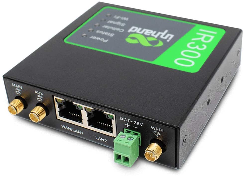](https://kb.egauge.net/uploads/images/gallery/2022-04/ir302.jpg) |
| ***Inhand Networks IR302*** |
The cellular antennas must be located on the outside of any enclosure. Even plastic enclosures can degrade or block a cellular signal.
1. If the modem is ordered with a data plan, an activation instruction sheet will be included with a SIM card. Insert the SIM card into the modem as shown above, ensuring the SIM card is in the "SIM 1" position. Follow the data plan activation instructions provided to activate the data plan. 2. Connect the DIN rail to either the left or right side of the modem using the included bracket and screws. 3. Locate a suitable location to install the cell modem. If installing in a Powered Enclosure Kit (PEK), mount on the DIN rail. 4. If using the PEK or other suitable enclosure, use the 2x short SMA extension cables to connect from the Cellular1 and Cellular2 connectors on the modem to create a bulkhead connector on the enclosure. 5. Connect the antennas to the bulkhead connectors on the enclosure, or directly to the cell modem if not using an enclosure. 6. Connect the power cord to the cellular modem. 7. Connect the eGauge meter via Ethernet to a LAN port on the modem. #### Detailed SIM card install instructions 1. Use the SIM card remover tool to eject the SIM card tray.| [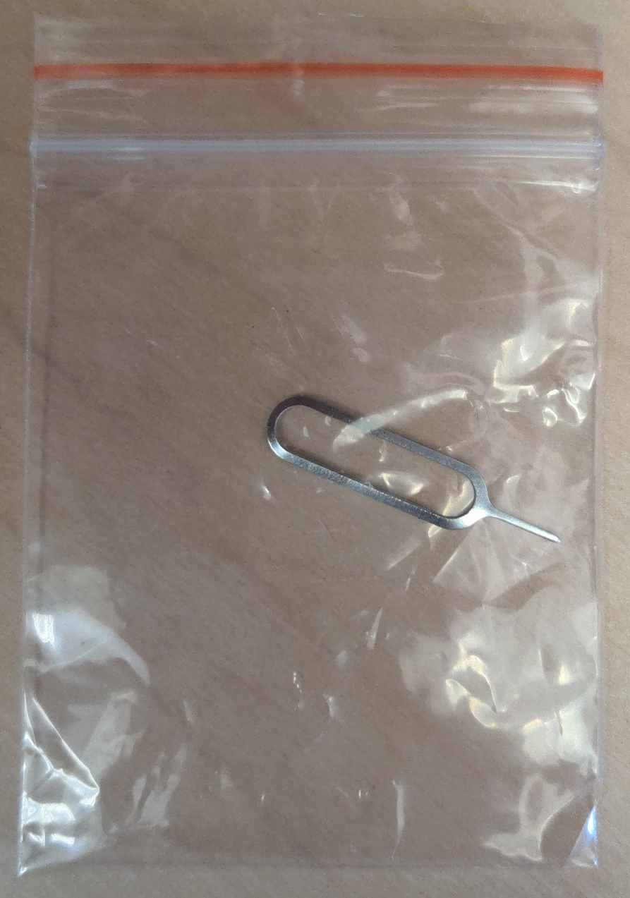](https://kb.egauge.net/uploads/images/gallery/2022-10/image.png) | [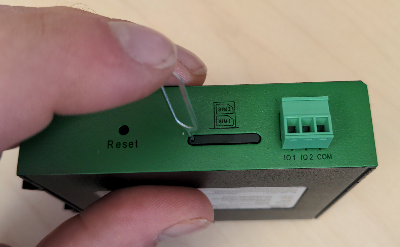](https://kb.egauge.net/uploads/images/gallery/2022-10/MRMimage.png) |
| *SIM card remover tool* | *Insert SIM card removal tool into SIM card ejection port* |
| [](https://kb.egauge.net/uploads/images/gallery/2022-10/TYBimage.png) | [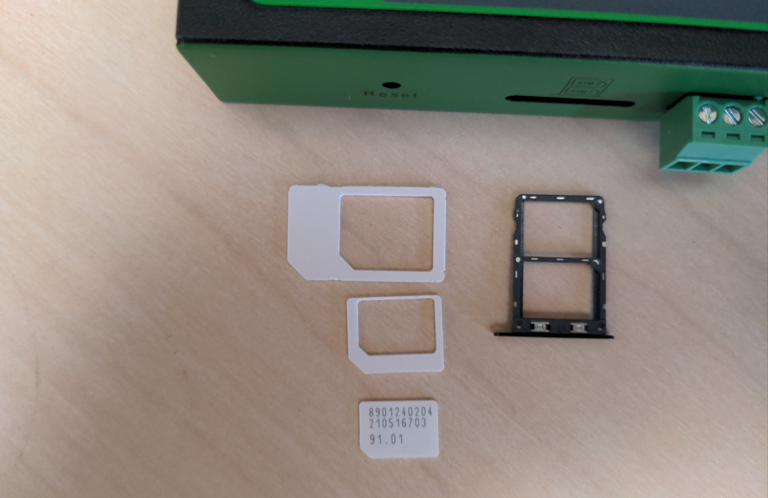](https://kb.egauge.net/uploads/images/gallery/2022-10/sGOimage.png) |
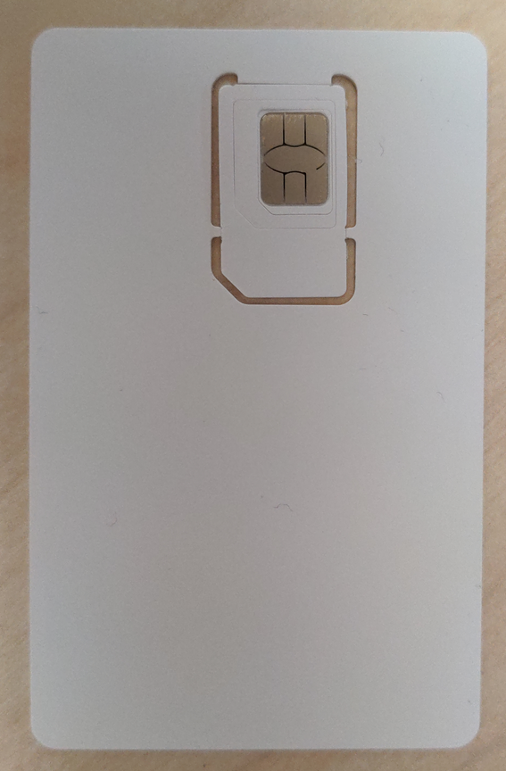
| *Full SIM card* | *SIM card with 2 outer shells removed* |
| [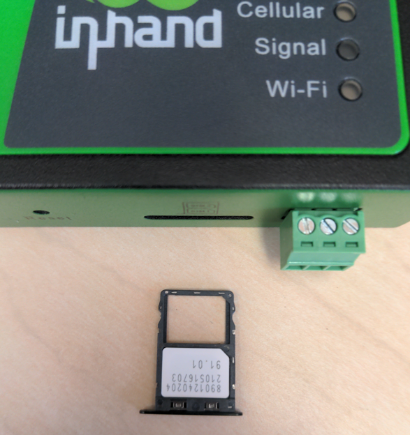](https://kb.egauge.net/uploads/images/gallery/2022-10/y2Iimage.png) |
| *SIM card in holder before inserted* |
Modems provided by eGauge are pre-configured to work on the T-Mobile network using data plans provided by eGauge Systems.
The default DHCP range of IR302 modems provided by eGauge is 192.168.2.2 to 192.168.2.100. Devices may be given static IPs in the range of 192.168.2.101 to 192.168.2.254. A particular static IP must not be used on more than one device on a single modem.
If the modem is not functioning and configuration may have been modified after shipment, perform a factory reset and upload the eGauge-specific cellular configuration if using a dataplan provided by eGauge Systems. ### LED indicator description The modem has a "Signal" LED with 3 different colors to indicate the signal strength level: Red: Signal strength 0-10 (Signal strength is weak, please check antenna and the signal strength of current location). Yellow: Signal strength 11-20 (signal strength is adequate, and the modem can be used). Green: Signal strength 21-30 (signal strong). The other LED behavior is described below:| **Power** **(Red)** | **Status** **(Green)** | **Cellular** **(Yellow)** | **Description** |
| Off | Off | Off | Powered Off |
| On | Off | Off | System failure |
| On | On | Off | The module or SIM card is not recognized |
| On | On | Blinking | Dialing (Connection attempt is being made) |
| On | On | On | Dialing Succeeded (A connection to the provider was made. This does not guarantee the SIM card data plan is active) |
| On | Blinking | On | Software Upgrade in progress |
| On | Blinking, then On | Off | A reset is being performed |
Modems provided by eGauge are pre-configured to work on the T-Mobile network using data plans provided by eGauge Systems. These steps are only needed if the modem was factory reset or configuration was modified. The APN for T-Mobile plans provided by eGauge is `iot.tmowholesale`
1. Download the [IR302 eGauge configuration for T-Mobile here.](https://kb.egauge.net/attachments/43) 2. Connect a computer to a LAN port of the cell modem. 3. Open a web browser to [http://192.168.2.1/](http://192.168.2.1/) and log in with username `adm` and password `123456`. [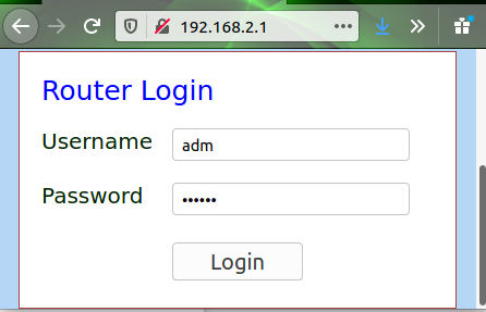](https://kb.egauge.net/uploads/images/gallery/2020-11/image-1605809939644.png) 4. The modem may prompt to opt-in to a User Experience Program from InHand. You may click "CANCEL" on this. It may be toggled on or off later in Services -> User Experience Plan. 5. Navigate to System -> Config Management. [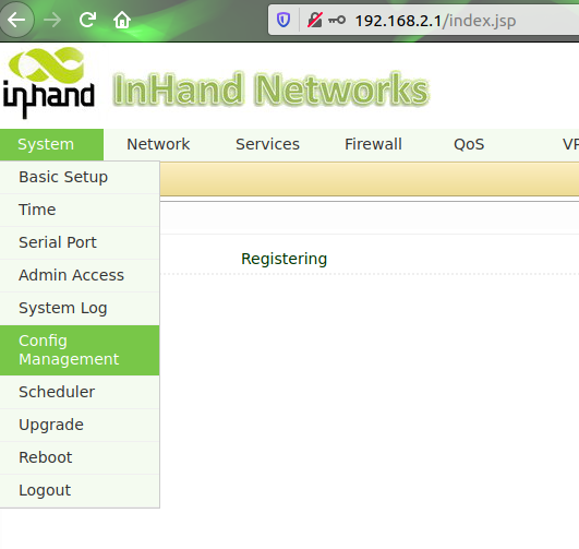](https://kb.egauge.net/uploads/images/gallery/2020-11/image-1605809785399.png) 6. Under "Router Configuration", click the "Browse" button and choose the file downloaded earlier. [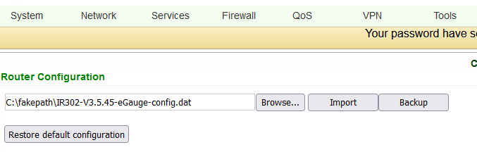](https://kb.egauge.net/uploads/images/gallery/2022-06/image-1655916417303.png) 7. Press "Import", choose "OK" when it asks if you are sure, and finally press "Reboot" when it prompts to be rebooted. [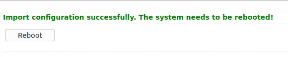](https://kb.egauge.net/uploads/images/gallery/2020-11/image-1605809825184.png) ### Additional diagnostics and troubleshooting The following pages provide information and diagnostics that can be helpful in identifying poor signal or other issues. Connect a computer to a LAN port of the modem and visit [http://192.168.2.1/](http://192.168.2.1/) logging in with username `adm` and password `123456`. If this does not work, perform a factory reset and initial configuration as described in the above sections.| **Page location** | **Description** |
| Tools -> Ping | Have the modem ping an external IP or domain. |
| Status -> Modem | Contains signal level, RSSI, SIM card number, network type and other modem-related information |
| Status -> Network Connections | Dialup (cellular) IP information from cellular provider |
| Status -> Device List | DHCP list of connected devices to the LAN ports |
| Status -> Log | Raw log from modem |
| **Condition** | **RSRP (dBm)** | **RSRQ (dB)** | **SINR (dB)** |
| Excellent ✓✓✓ | `>=-80` | `>=-10` | `>=20` |
| Good ✓✓ | `-80 to -90` | `-10 to -15` | `13 to 20` |
| Medium ✓ | `-90 to -100` | `-15 to -20` | `0 to 13` |
| Weak | `<=-100` | `<-20` | `<=0` |
Dataplans sold by eGauge Systems are intended for use with models sold by eGauge Systems and in the U.S.
You must have an eGauge.net account before activating a data plan. If you do not already have an eGauge.net account, please create and confirm an eGauge.net account at **[https://www.egauge.net/account/register/](https://www.egauge.net/account/register/)**. To confirm the account you must click on a link that is emailed to you.
Data Plans belong to the eGauge.net user and email that activated it. Invoices and bills will be sent to the eGauge.net account email that activated the data plan.
Only data plans sold directly by eGauge Systems may be activated through the data plan portal. Only modems currently and previously sold by eGauge Systems are supported.
For information on using the IR302 modem provided by eGauge Systems, view our **[IR302 product page](https://kb.egauge.net/egauge.net/support/m/ir302)**.
## Data Plan Service eGauge Systems provides cellular modems along with a SIM card that provides T-Mobile service compatible with modems sold by eGauge Systems in the U.S. ## Modem Information For particular information on your modem, including hardware and SIM card installation and configuration, please find the model number in our [Communication Hardware](https://kb.egauge.net/books/egauge-hardware-product-pages/chapter/communication-hardware) chapter. All modems sold by eGauge Systems are pre-configured to work with the dataplans provided. ### Data Plan Activation Each Data Plan sold is provided with a sheet of paper with a QR code and link to activate the plan. An example is shown here: [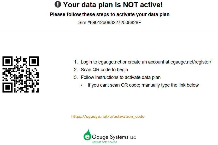](https://kb.egauge.net/uploads/images/gallery/2022-08/image-1661811280544.png) *Note: the QR code and "link below" link goes to a unique URL for that particular data plan activation* If you do not already have an eGauge.net account you will be requested to create one. After you create and confirm the account Scan the QR code or enter the link and follow the instructions for activating the data plan. eGauge Systems utilizes [Stripe Billing ](https://stripe.com/)for billing and recurring payments. #### Without QR code, link, or paperwork If you do not have the QR code or link from the paperwork that came with the SIM card, you may log into eGauge.net and activate the data plan by clicking Support → Activate a Data Plan, and entering the SIM card number in the form. [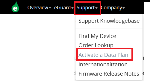](https://kb.egauge.net/uploads/images/gallery/2022-08/image-1661813268537.png) ### Data Plan Cancellation To cancel a data plan, log into your Data Plan Management portal as shown below and choose the Cancel button. If payment lapses for a user's data plans, the plans will automatically be cancelled. ## Data Plan Management eGauge.net provides a simple portal to manage data plans purchased and activated through eGauge Systems. To begin, log into your eGauge.net account which has one or more active data plans. Click your user in the upper right-hand menu and choose "Account Settings": [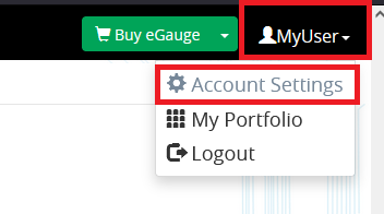](https://kb.egauge.net/uploads/images/gallery/2022-08/image-1661813429227.png) Next, choose "Manage Data Plans": [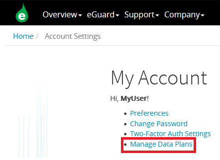](https://kb.egauge.net/uploads/images/gallery/2022-08/image-1661813523726.png) You will be presented with a list of data plans that have been activated under your account. Plans may be cancelled or reactivated here (in the case you cancelled them after activating). [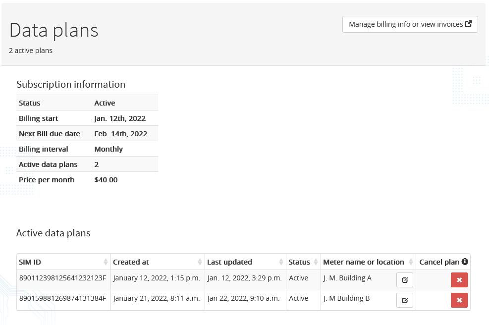](https://kb.egauge.net/uploads/images/gallery/2022-08/image-1661818583404.png) You may cancel plans using the "Cancel plan" button. After a plan is cancelled, it will display in your portal with a "reactivate" button. A deactivated plan may be activated by a different user, for example if a different user is responsible for ongoing payment of a data plan, it may be deactivated and the new user may activate it using either the original QR code or link the data plan came with, or using the "Activate a Data Plan" link in the Support menu on eGauge.net. It is recommended to add a description for the particular data plan by clicking the notepad icon under "Meter name or location". ## Billing All billing for data plans is performed through Stripe, under a single bill that starts when the first data plan on a users account is activated. Any additional plans activated while an existing data plan is active will be billed for on the billing date of the first plan activation date. You may update and set the default credit card and view previous bills through the portal shown above, using the "Manage billing info or view invoices" button in the upper right-hand corner of the page. Upcoming payment notifications and invoices are sent to the email used when registering the eGauge.net account that activated the plan. ## Transferring plans to another user A data plan cannot be "transferred" between users as the billing information is linked to Stripe and the eGauge.net user. To transfer a plan to another user, the original activator of the plan must [cancel the plan](#bkmrk-data-plan-cancellati), and the new user may [activate the plan](#bkmrk-data-plan-activation) using the QR code or entering the SIM card number manually. # Enclosures and Mounting Hardware Complete kits which simplify installation on a variety of electrical services. # Powered Enclosure Kit (120/240VAC, 120/208VAC) ##### [ Visit the online store page](https://store.egauge.net/powered_enclosure_kit_120 "Visit the online store now!") ##### SKU: PEK-120/PEK-120-XL The Powered Enclosure Kit is designed for installation of the eGauge in combination with one of several communication protocol devices.| [](https://s3.amazonaws.com/cdn.freshdesk.com/data/helpdesk/attachments/production/25012074201/original/8F0SdQNeWoN6lXV61pGY_utqPRGAy4wN6g.png?1562968857) | [](https://s3.amazonaws.com/cdn.freshdesk.com/data/helpdesk/attachments/production/25012074196/original/20XnVNM84Hp2SC0SIcjHnXK6IHFEnEcx5A.png?1562968833) |
| *Components included* | *Enclosure* |
| [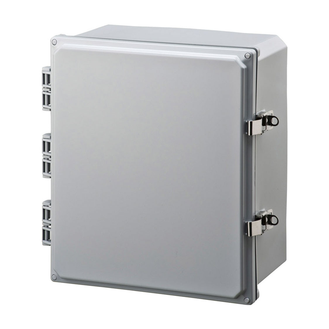](https://kb.egauge.net/uploads/images/gallery/2020-06/hinged-enclosure.jpg) |
| *Hinged Enclsosure* |
| [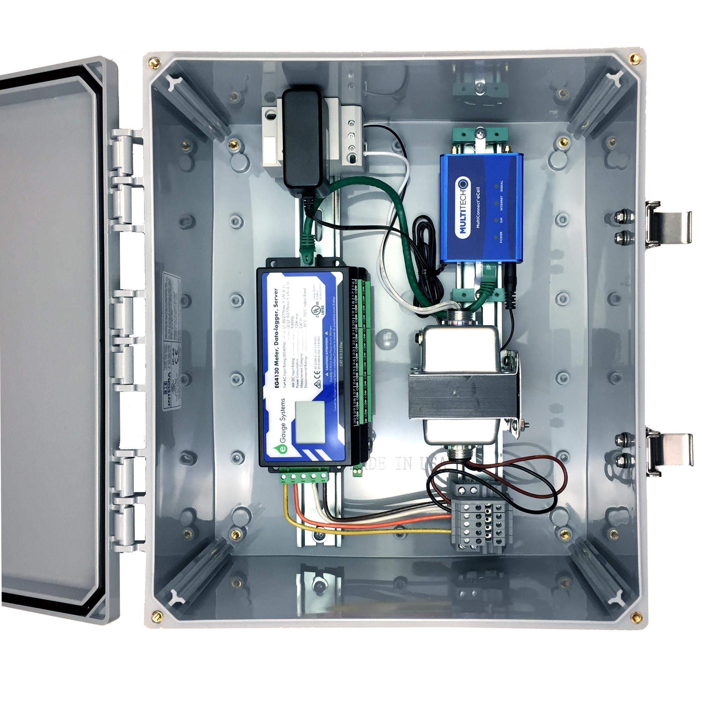](https://kb.egauge.net/uploads/images/gallery/2020-06/powered_enclosure_kit_277-pek277.jpg) |
| *277/480VAC Powered Enclosure Kit* |
Make sure to only use the included machine screws for mounting the DIN clip or bracket to the eGauge. Other screws could be too long and damage the meter.
| [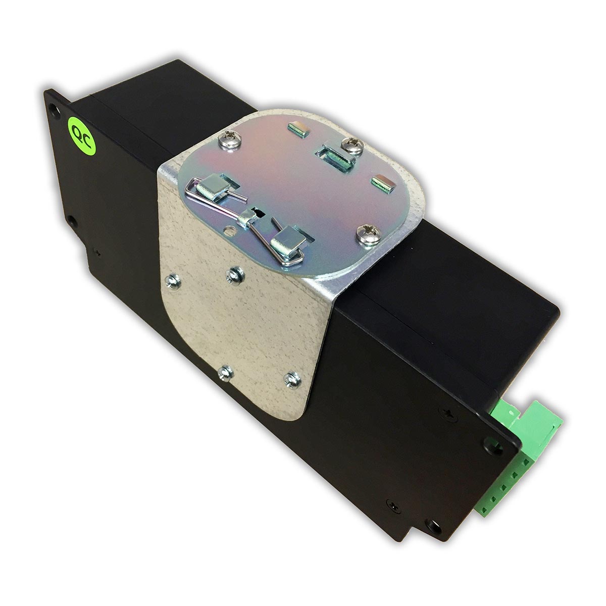](https://kb.egauge.net/uploads/images/gallery/2020-06/eg4xxx-mountingkit-mounted-side.jpg) |
| *eGauge Mouting Kit* |
| [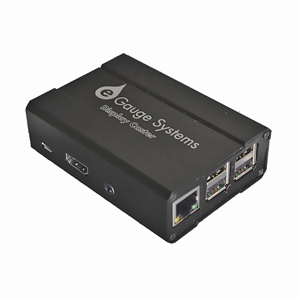](https://kb.egauge.net/uploads/images/gallery/2020-06/edc-display-caster.jpg) |
| *eGauge Display Caster* |
The default password for the display caster is printed on the paper attached to the manual, as well as inside the box with the eGauge Display Caster. The password can be changed during setup.
Do not leave keyboard/mouse, or USB ports accessible in public kiosk display
1. Connect keyboard and mouse via USB 2. Connect HDMI to television or monitor 3. Apply power using the 120V supply adapter, or USB-to-USB cable 4. Configure network, timezone, and device to display and save as default (see [Display Caster Manual](https://www.egauge.net/media/support/docs/egauge-display-caster-manual.pdf) for software setup information). ### Software configuration Information - Ensure timezone is set correctly - Ensure default kiosk is saved Follow the [Display Caster Manual](https://kb.egauge.net/books/other-hardware-documentation/page/egauge-display-caster-manual) for software setup. #### Factory Reset Connect a keyboard and enter the factory reset code for your version of the display caster. You may need to try multiple key combinations depending on when your display caster was purchased. There is no danger in entering a key combination for a different model. Current model: `ctrl+shift+f` simultaneously. Previous model: `shift+escape, f, r, tab` one at a time. Legacy model: `ctrl+shift+j` simultaneously. ## Documents - [Display Caster Manual (current version)](https://kb.egauge.net/books/other-hardware-documentation/page/egauge-display-caster-manual) - [Display Caster Manual (previous version)](https://www.egauge.net/media/support/docs/egauge-display-caster-manual.pdf) - [Display Caster Manual (old version)](https://www.egauge.net/media/support/docs/egauge-display-caster-manual-old.pdf) # 12 Volt Power Supply ##### [ Visit the online store page](https://store.egauge.net/12v_power_supply "Visit the online store now!") ##### SKU: PSU12V The 12 Volt Power supply is a standard power supply to convert 100-240VAC @ 0.5A (50/60Hz) to +12VDC @ 1A used to power the BF430 RS485-to-Ethernet adapter, CR-Magnetics DC CTs and other powered devices. May be used on 240VAC services with the appropriate adapter (not included).| [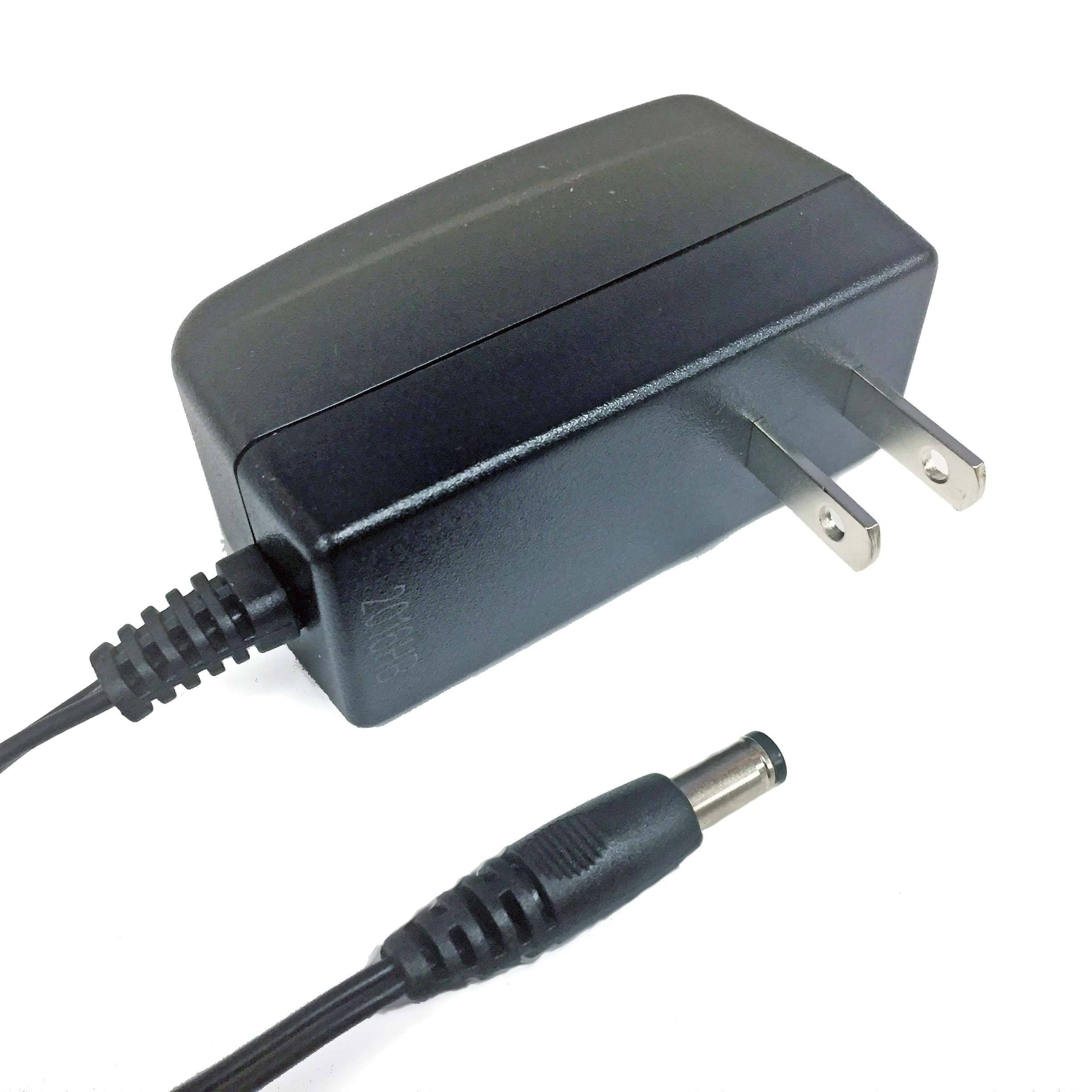](https://kb.egauge.net/uploads/images/gallery/2020-06/12v-power-supply.jpg) |
| *12V Power Supply* |
Stepdown transformers are intended only to power 120V equipment off higher voltage service. To measure 480V delta systems (no neutral), 600V delta systems (no neutral), or 347/600V Wye, please use the [EV1000 High Voltage Sensors](https://egauge.net/support/m/ev1000).
| [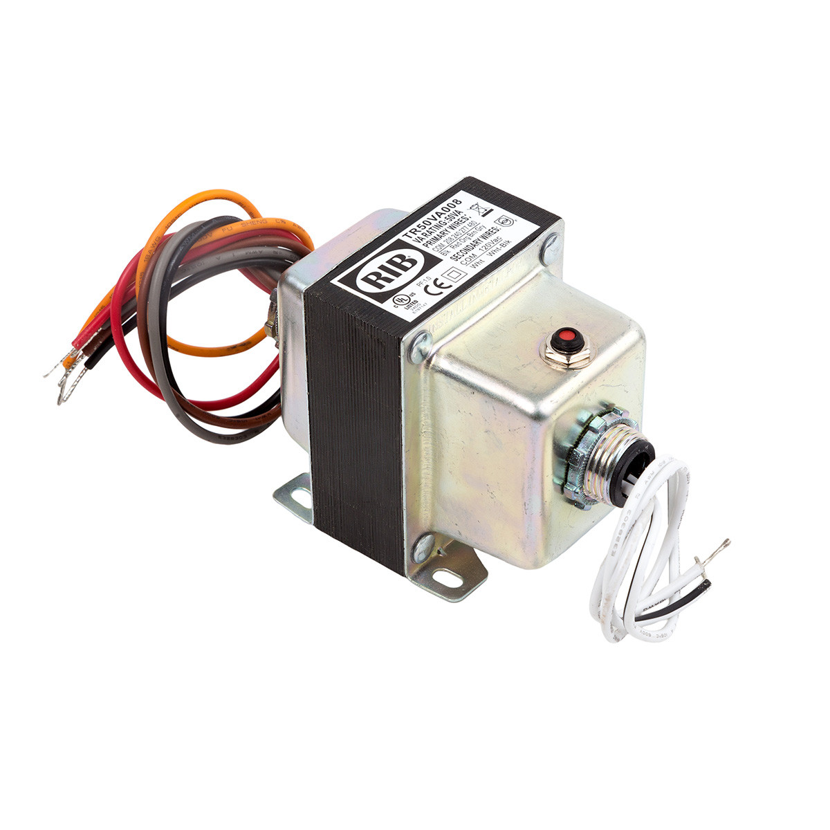](https://kb.egauge.net/uploads/images/gallery/2020-06/step-down-fdt-tr50va.jpg) |
| *Step-down transformer (480/277/240/208 to 120V)* |
Transformers provided by eGauge are 50VA (50 watts limit at 1.0 power factor, lower wattage when power factor < 1). They are intended to be used for powering a small amount of equipment provided by eGauge. Attempting to supply loads ~50VA or higher will cause the transformer to trip and require a manual reset.
## Specifications #### [Full specs (data-sheet PDF)](https://www.egauge.net/media/support/docs/TR50VA008.pdf "Full specs (data-sheet PDF)") - VA Rating: 50 - Frequency: 50/60 Hz - Mounting: Foot & Dual Threaded Hubs - Over Current Protection: Circuit Breaker - Dimensions: 3.440 ̋ x 2.510 ̋ x 3.012 ̋ (w/ .500 ̋ NPT Hubs) - Wire Length: 9.5 ̋ Typical w/ .5 ̋ Strip - Operating Temperature: -30 to 140° F - MTBF: 100,000 Hours @ 77° F - Construction: Split-Bobbin - Weight: 3.04 lbs. - Approvals: UL5085-2 Listed General Purpose, US / Canada, CE, RoHS ## Hardware included - Step-down transformer ## Assembly/installation information Follow instructions included with transformer, ensure correct primary and secondary wires are used. ## Documents [Spec Sheet](https://www.egauge.net/media/support/docs/TR50VA008.pdf) ## Related Information - [277V Powered Enclosure Kit](https://kb.egauge.net/books/egauge-hardware-product-pages/page/product-page-powered-enclosure-kit-%28277480vac%29 "Product Page: Powered Enclosure Kit (277/480VAC)") - [Potential Transformer Configuration](https://kb.egauge.net/books/egauge-meter-configuration/page/potential-transformer-configuration "Potential Transformer Configuration") - [Monitoring 480V and 600V systems](https://kb.egauge.net/books/egauge-installation/page/monitoring-480v-and-600v-delta-systems) - [EV1000 High Voltage Sensor](https://egauge.net/support/m/ev1000) # Power Relay Module (PRM3) ##### [ Visit the online store page](https://store.egauge.net/Power-Relay-Module "Visit the online store now!") ##### Model: PRM3**Polyphase equipment control danger warning** When controlling single-phase or three-phase loads that have more than one currently-carrying conductors (e.g., hot lines, not neutral or ground), be sure to control the relay inputs for the polyphase load simultaneously [using mask controls](https://kb.egauge.net/books/other-hardware-documentation/page/mask-control), or there is risk of having the load operate without all phases which may cause damage to the equipment.
Read the [PRM3 Owner's Manual](https://www.egauge.net/media/support/docs/prm3-manual.pdf) for safety and full control information.
For control: requires eGauge Core or Pro, or a third party controller that supports Modbus RTU or SCPI.
By default, the PRM3 is configured with a 10-second minimum open/close duration to minimize unintentional wear on the relays or rapid load switching. For example, by default when a relay input is opened, it will remain in the open state for at least 10 seconds before a command to close it will be acknowledged. This minimum delay may be reconfigured between 0 seconds and 4 minutes and 15 seconds using Modbus or SCPI commands.
The eGauge Power Relay Module is a versatile device intended to control up to three 240V AC/15 A resistive loads or motors up to 15 FLA (80 LRA). The relays can be opened and closed individually or synchronously, enabling the switching of up to three single-phase loads, one split-phase and one single-phase load, or one three-phase load. Intended applications include Remote control of air conditioners, heaters, refrigerators, office-automation, and similar equipment.| [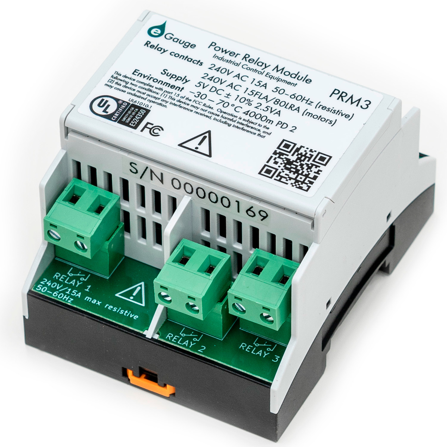](https://kb.egauge.net/uploads/images/gallery/2023-04/prm3-1.jpg) | [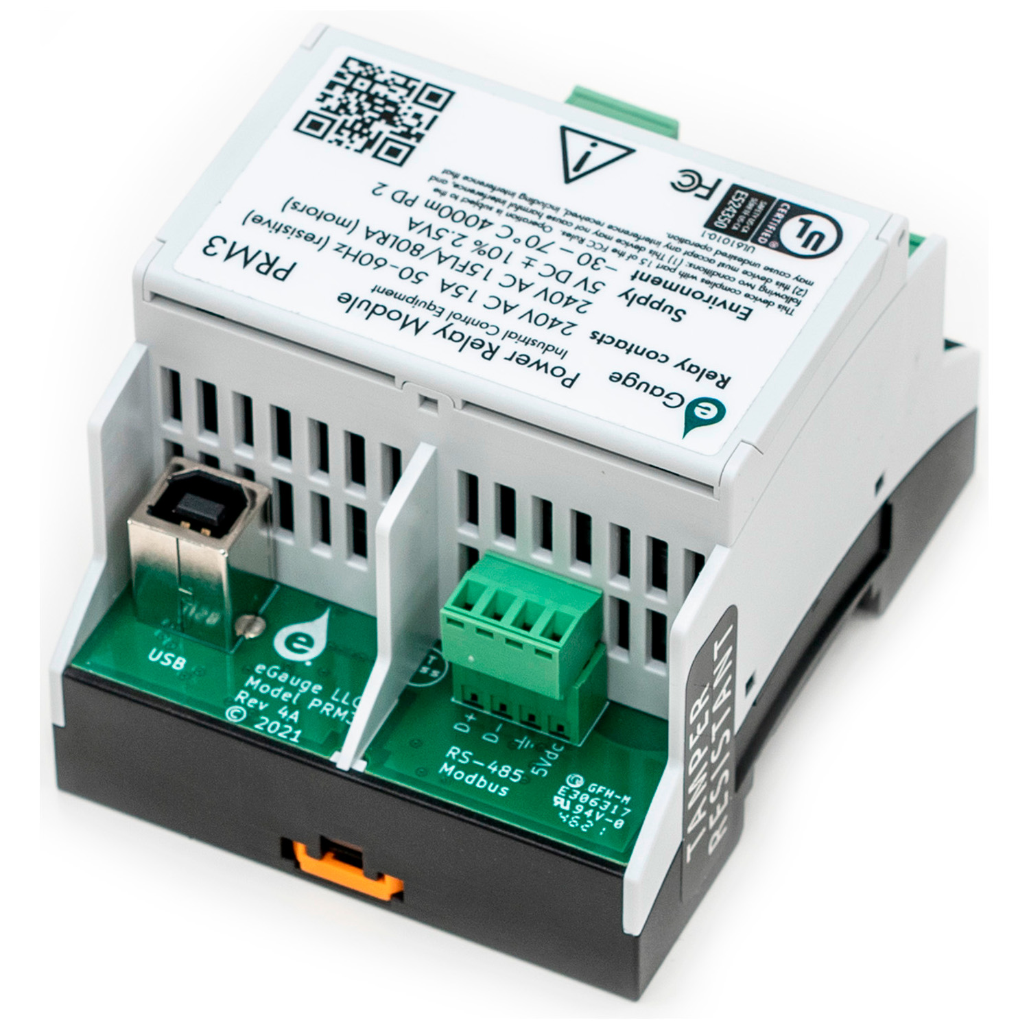](https://kb.egauge.net/uploads/images/gallery/2023-04/prm3-2.jpg) |
| *"Front" of PRM3 with relay contacts* | *"Back" of PRM3 with USB and RS485 for power and communication* |
Be sure to use **[mask commands](https://kb.egauge.net/books/other-hardware-documentation/page/mask-control)** for controlling polyphase loads that use multiple PRM3 contacts!
The eGauge PRM3 may be controlled through several different options: - [eGauge Meter Interactive Dashboard control](https://kb.egauge.net/books/other-hardware-documentation/page/dashboard-control-of-prm3) - [eGauge Meter Lua Scripting](https://kb.egauge.net/books/other-hardware-documentation/page/lua-scripting-with-prm3) - [eGauge Meter JSON WebAPI control](https://kb.egauge.net/books/other-hardware-documentation/page/json-webapi-relay-control) - [Modbus RTU](https://kb.egauge.net/books/other-hardware-documentation/page/modbus-control-of-prm3) (RS-485 Serial) - [SCPI](https://kb.egauge.net/books/other-hardware-documentation/page/scpi-control-of-prm3) (USB via a CDC ACM virtual serial port) ## Documents - [Data Sheet](https://www.egauge.net/media/support/docs/PRM3-datasheet-web.pdf) ## Related Information - [eGauge meter Lua Scripting](https://kb.egauge.net/books/advanced-egauge-operation/chapter/lua-scripting) - [Mobile-friendly dashboard](https://kb.egauge.net/books/egauge-meter-ui/page/dashboard) ## Diagrams #### PRM3 overview [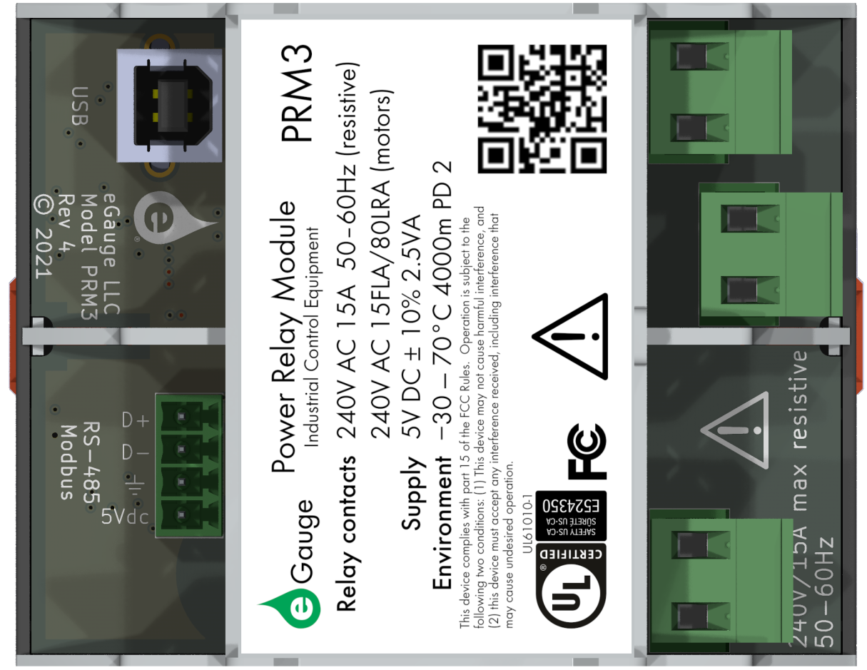](https://kb.egauge.net/uploads/images/gallery/2023-02/image.png) #### Typical RS-485 Wiring Example [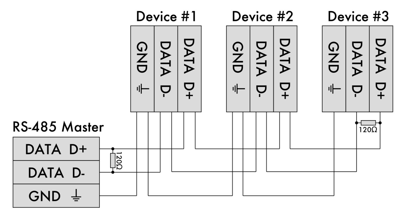](https://kb.egauge.net/uploads/images/gallery/2023-02/72Rimage.png) #### 3-phase load wiringNeutral may or may not be used depending on the load.
Be sure to control all 3 relay inputs simultaneously when turning on or off the three-phase load.
[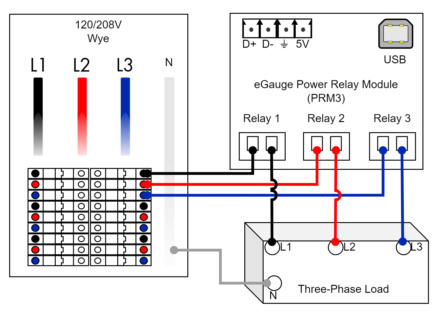](https://kb.egauge.net/uploads/images/gallery/2023-02/prm3-3ph-load.png) #### Single-phase load wiringNeutral may or may not be used depending on the load.
Be sure to control the two relay inputs simultaneously when turning on or off the single-phase load.
[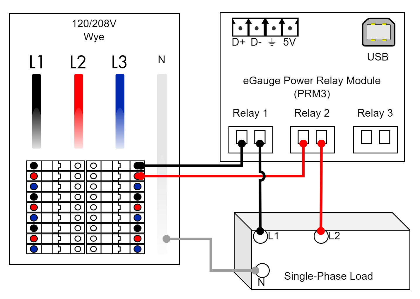](https://kb.egauge.net/uploads/images/gallery/2023-02/prm3-2ph-load.png) #### Split-phase load wiringNeutral may or may not be used depending on the load.
[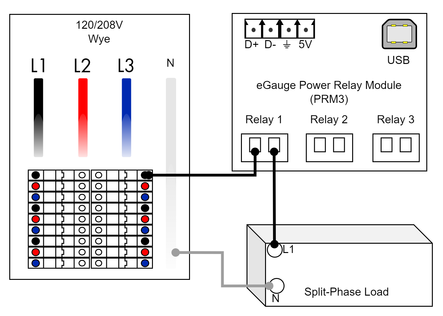](https://kb.egauge.net/uploads/images/gallery/2023-02/prm3-1ph-load.png) ## Related Material - [PRM3 software documentation](https://kb.egauge.net/books/other-hardware-documentation/chapter/power-relay-module-prm3-software-documentation) - [Lua Scripting](https://kb.egauge.net/books/advanced-egauge-operation/chapter/lua-scripting) # Connectors and cables Connectors and cables which connect directly to the eGauge meter. # 2-pin CT Plug ##### [ Visit the online store page](https://store.egauge.net/ct_plug "Visit the online store now!") *Original manufacturer part number: Tyco model 284506-2*Do not connect unsupported sensors to eGauge meter inputs or damage may occur.
- CTs purchased from eGauge already have 2-pin connectors affixed - The eGauge Core and Pro meters already have a 2-pin plug connected to the DC voltage port|  |
| *2-pin Plug* |
|   |
| *eGauge Power Whip* |
| 208V Color | Connection |
|---|---|
| White | Neutral |
| Black | L1 |
| Red | L2 |
| Blue | L3 |
| 277V Color | Connection |
|---|---|
| White | Neutral |
| Yellow | L1 |
| Orange | L2 |
| Brown | L3 |
| Single-phase Color | Connection |
|---|---|
| White | Neutral |
| Black | L1 |
| Red | L2 |
| Blue | \[REMOVED\] |
If extending CT leads, make splices using the [**CT extension pack**](https://store.egauge.net/ct_extension_pack) or by soldering. Wire nuts do not provide a stable enough connection and should **not** be used.
|  |  |
This is a replacement part for eGauge meters. Every eGauge meter includes a 5-pin plug with it.
| **** |
| *eGauge 5-pin Power Plug* |
**Not for use** with the ESH044 Sensor hub, if connected to the Sensor Hub 5 Vdc 2-pin voltage port **sensor damage will occur**.
When measuring AC power, the AC voltage inputs must be utilized, power cannot be calculated otherwise. The EG4xxx DC Power Supply may be used to power an eGauge while it is measuring high voltage, but the AC inputs (L1/L2/L3/N) must be connected to the system being monitored either by connections to the AC Mains power connector or via [EV1000](https://store.egauge.net/High-Voltage-Sensor) sensors.
|   |
| *eGauge Test Power cable* |
The EG4xxx DC Power Supply must be connected to the Ldc terminal. If connected to a Sensor/CT input damage may occur
1. Select the appropriate receptacle adapter. 2. Clip the receptacle adapter into the body of the power supply. 3. Connect the two pin plug to the Ldc terminal (next to the five pin power plug).