| [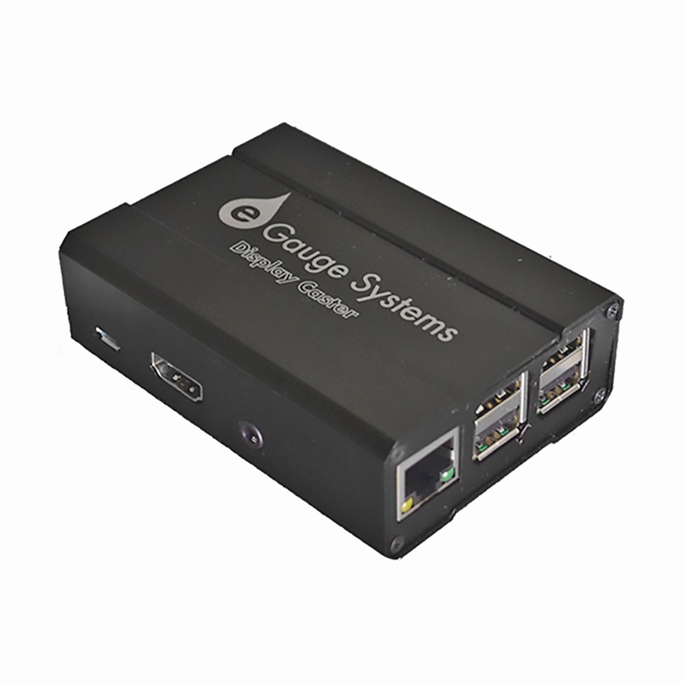](https://kb.egauge.net/uploads/images/gallery/2020-06/edc-display-caster.jpg) |
| *eGauge Display Caster* |
The default password for the display caster is printed on the paper attached to the manual, as well as inside the box with the eGauge Display Caster. The password can be changed during setup.
Do not leave keyboard/mouse, or USB ports accessible in public kiosk display
1. Connect keyboard and mouse via USB 2. Connect HDMI to television or monitor 3. Apply power using the 120V supply adapter, or USB-to-USB cable 4. Configure network, timezone, and device to display and save as default (see [Display Caster Manual](https://www.egauge.net/media/support/docs/egauge-display-caster-manual.pdf) for software setup information). ### Software configuration Information - Ensure timezone is set correctly - Ensure default kiosk is saved Follow the [Display Caster Manual](https://kb.egauge.net/books/other-hardware-documentation/page/egauge-display-caster-manual) for software setup. #### Factory Reset Connect a keyboard and enter the factory reset code for your version of the display caster. You may need to try multiple key combinations depending on when your display caster was purchased. There is no danger in entering a key combination for a different model. Current model: `ctrl+shift+f` simultaneously. Previous model: `shift+escape, f, r, tab` one at a time. Legacy model: `ctrl+shift+j` simultaneously. ## Documents - [Display Caster Manual (current version)](https://kb.egauge.net/books/other-hardware-documentation/page/egauge-display-caster-manual) - [Display Caster Manual (previous version)](https://www.egauge.net/media/support/docs/egauge-display-caster-manual.pdf) - [Display Caster Manual (old version)](https://www.egauge.net/media/support/docs/egauge-display-caster-manual-old.pdf) # 12 Volt Power Supply ##### [ Visit the online store page](https://store.egauge.net/12v_power_supply "Visit the online store now!") ##### SKU: PSU12V The 12 Volt Power supply is a standard power supply to convert 100-240VAC @ 0.5A (50/60Hz) to +12VDC @ 1A used to power the BF430 RS485-to-Ethernet adapter, CR-Magnetics DC CTs and other powered devices. May be used on 240VAC services with the appropriate adapter (not included).| [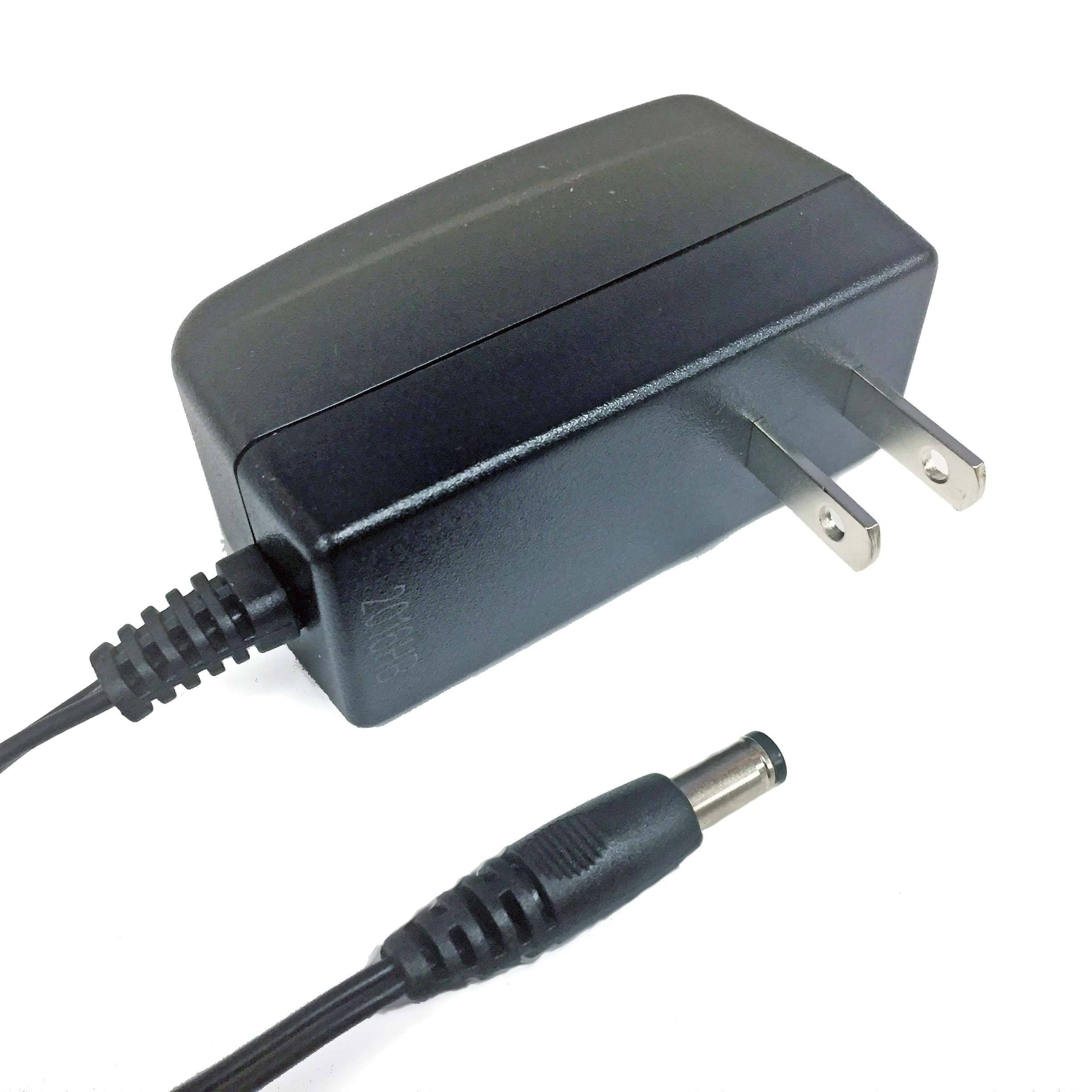](https://kb.egauge.net/uploads/images/gallery/2020-06/12v-power-supply.jpg) |
| *12V Power Supply* |
Stepdown transformers are intended only to power 120V equipment off higher voltage service. To measure 480V delta systems (no neutral), 600V delta systems (no neutral), or 347/600V Wye, please use the [EV1000 High Voltage Sensors](https://egauge.net/support/m/ev1000).
| [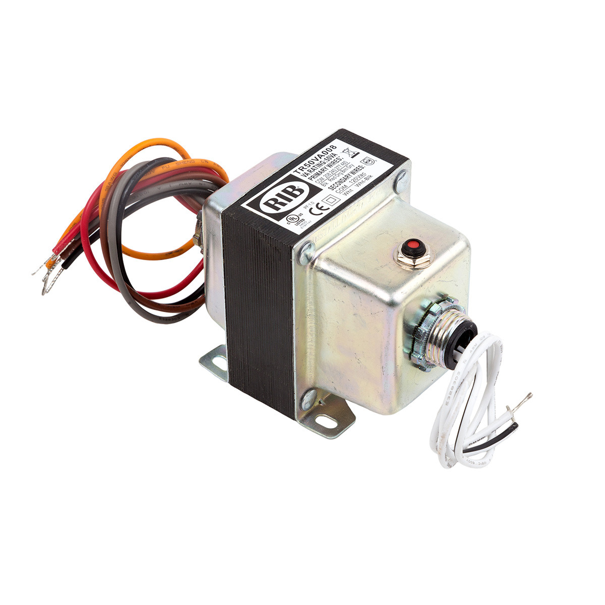](https://kb.egauge.net/uploads/images/gallery/2020-06/step-down-fdt-tr50va.jpg) |
| *Step-down transformer (480/277/240/208 to 120V)* |
Transformers provided by eGauge are 50VA (50 watts limit at 1.0 power factor, lower wattage when power factor < 1). They are intended to be used for powering a small amount of equipment provided by eGauge. Attempting to supply loads ~50VA or higher will cause the transformer to trip and require a manual reset.
## Specifications #### [Full specs (data-sheet PDF)](https://www.egauge.net/media/support/docs/TR50VA008.pdf "Full specs (data-sheet PDF)") - VA Rating: 50 - Frequency: 50/60 Hz - Mounting: Foot & Dual Threaded Hubs - Over Current Protection: Circuit Breaker - Dimensions: 3.440 ̋ x 2.510 ̋ x 3.012 ̋ (w/ .500 ̋ NPT Hubs) - Wire Length: 9.5 ̋ Typical w/ .5 ̋ Strip - Operating Temperature: -30 to 140° F - MTBF: 100,000 Hours @ 77° F - Construction: Split-Bobbin - Weight: 3.04 lbs. - Approvals: UL5085-2 Listed General Purpose, US / Canada, CE, RoHS ## Hardware included - Step-down transformer ## Assembly/installation information Follow instructions included with transformer, ensure correct primary and secondary wires are used. ## Documents [Spec Sheet](https://www.egauge.net/media/support/docs/TR50VA008.pdf) ## Related Information - [277V Powered Enclosure Kit](https://kb.egauge.net/books/egauge-hardware-product-pages/page/product-page-powered-enclosure-kit-%28277480vac%29 "Product Page: Powered Enclosure Kit (277/480VAC)") - [Potential Transformer Configuration](https://kb.egauge.net/books/egauge-meter-configuration/page/potential-transformer-configuration "Potential Transformer Configuration") - [Monitoring 480V and 600V systems](https://kb.egauge.net/books/egauge-installation/page/monitoring-480v-and-600v-delta-systems) - [EV1000 High Voltage Sensor](https://egauge.net/support/m/ev1000) # Power Relay Module (PRM3) ##### [ Visit the online store page](https://store.egauge.net/Power-Relay-Module "Visit the online store now!") ##### Model: PRM3**Polyphase equipment control danger warning** When controlling single-phase or three-phase loads that have more than one currently-carrying conductors (e.g., hot lines, not neutral or ground), be sure to control the relay inputs for the polyphase load simultaneously [using mask controls](https://kb.egauge.net/books/other-hardware-documentation/page/mask-control), or there is risk of having the load operate without all phases which may cause damage to the equipment.
Read the [PRM3 Owner's Manual](https://www.egauge.net/media/support/docs/prm3-manual.pdf) for safety and full control information.
For control: requires eGauge Core or Pro, or a third party controller that supports Modbus RTU or SCPI.
By default, the PRM3 is configured with a 10-second minimum open/close duration to minimize unintentional wear on the relays or rapid load switching. For example, by default when a relay input is opened, it will remain in the open state for at least 10 seconds before a command to close it will be acknowledged. This minimum delay may be reconfigured between 0 seconds and 4 minutes and 15 seconds using Modbus or SCPI commands.
The eGauge Power Relay Module is a versatile device intended to control up to three 240V AC/15 A resistive loads or motors up to 15 FLA (80 LRA). The relays can be opened and closed individually or synchronously, enabling the switching of up to three single-phase loads, one split-phase and one single-phase load, or one three-phase load. Intended applications include Remote control of air conditioners, heaters, refrigerators, office-automation, and similar equipment.| [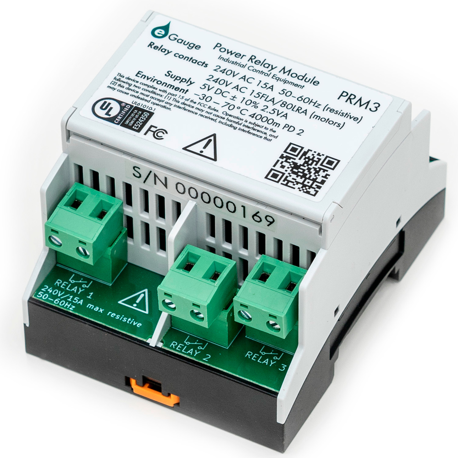](https://kb.egauge.net/uploads/images/gallery/2023-04/prm3-1.jpg) | [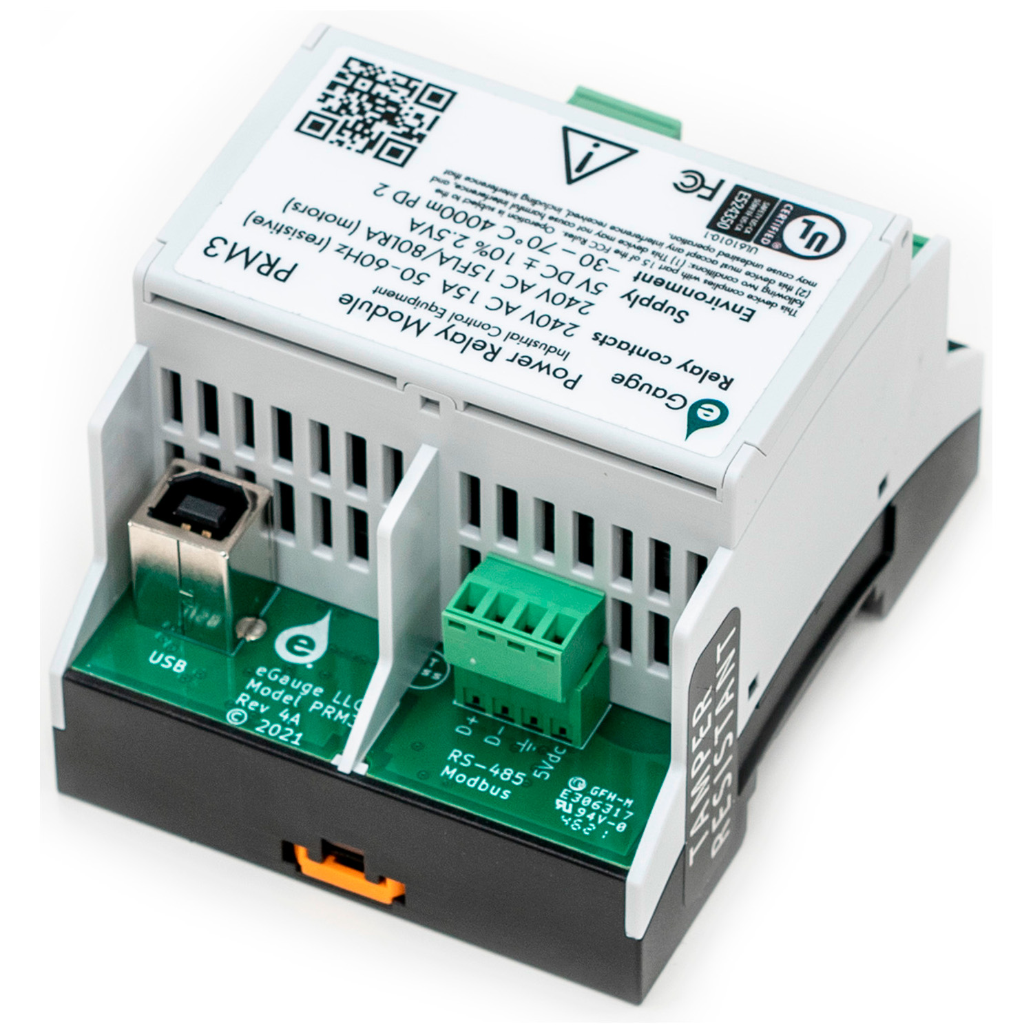](https://kb.egauge.net/uploads/images/gallery/2023-04/prm3-2.jpg) |
| *"Front" of PRM3 with relay contacts* | *"Back" of PRM3 with USB and RS485 for power and communication* |
Be sure to use **[mask commands](https://kb.egauge.net/books/other-hardware-documentation/page/mask-control)** for controlling polyphase loads that use multiple PRM3 contacts!
The eGauge PRM3 may be controlled through several different options: - [eGauge Meter Interactive Dashboard control](https://kb.egauge.net/books/other-hardware-documentation/page/dashboard-control-of-prm3) - [eGauge Meter Lua Scripting](https://kb.egauge.net/books/other-hardware-documentation/page/lua-scripting-with-prm3) - [eGauge Meter JSON WebAPI control](https://kb.egauge.net/books/other-hardware-documentation/page/json-webapi-relay-control) - [Modbus RTU](https://kb.egauge.net/books/other-hardware-documentation/page/modbus-control-of-prm3) (RS-485 Serial) - [SCPI](https://kb.egauge.net/books/other-hardware-documentation/page/scpi-control-of-prm3) (USB via a CDC ACM virtual serial port) ## Documents - [Data Sheet](https://www.egauge.net/media/support/docs/PRM3-datasheet-web.pdf) ## Related Information - [eGauge meter Lua Scripting](https://kb.egauge.net/books/advanced-egauge-operation/chapter/lua-scripting) - [Mobile-friendly dashboard](https://kb.egauge.net/books/egauge-meter-ui/page/dashboard) ## Diagrams #### PRM3 overview [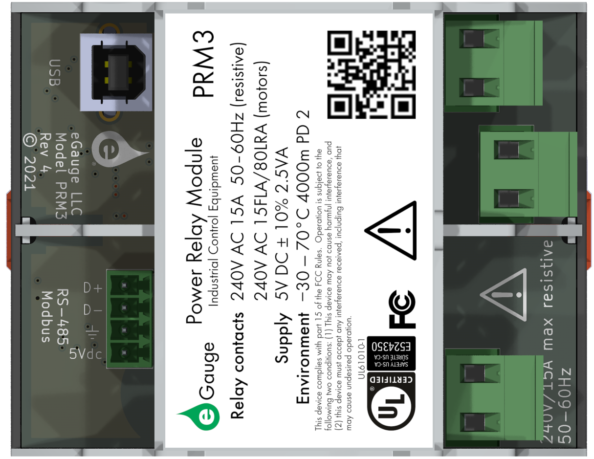](https://kb.egauge.net/uploads/images/gallery/2023-02/image.png) #### Typical RS-485 Wiring Example [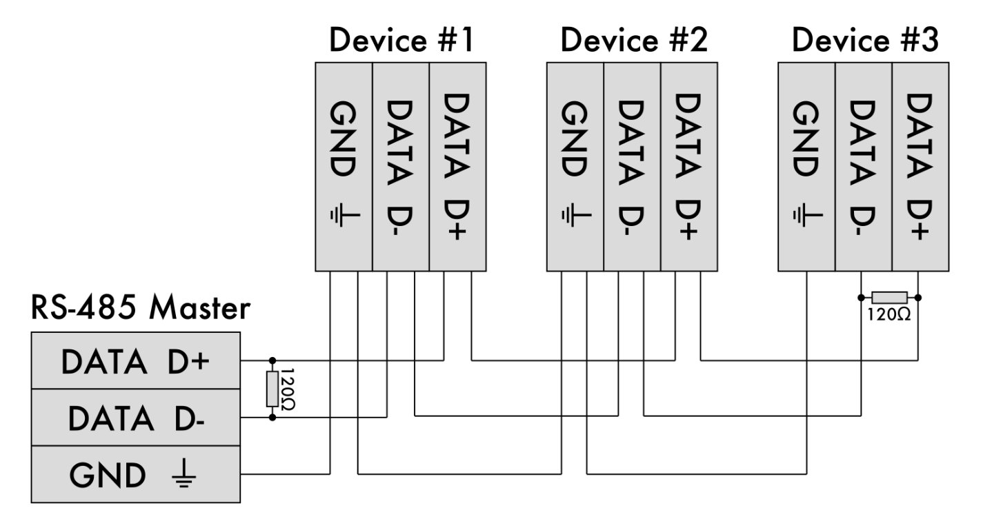](https://kb.egauge.net/uploads/images/gallery/2023-02/72Rimage.png) #### 3-phase load wiringNeutral may or may not be used depending on the load.
Be sure to control all 3 relay inputs simultaneously when turning on or off the three-phase load.
[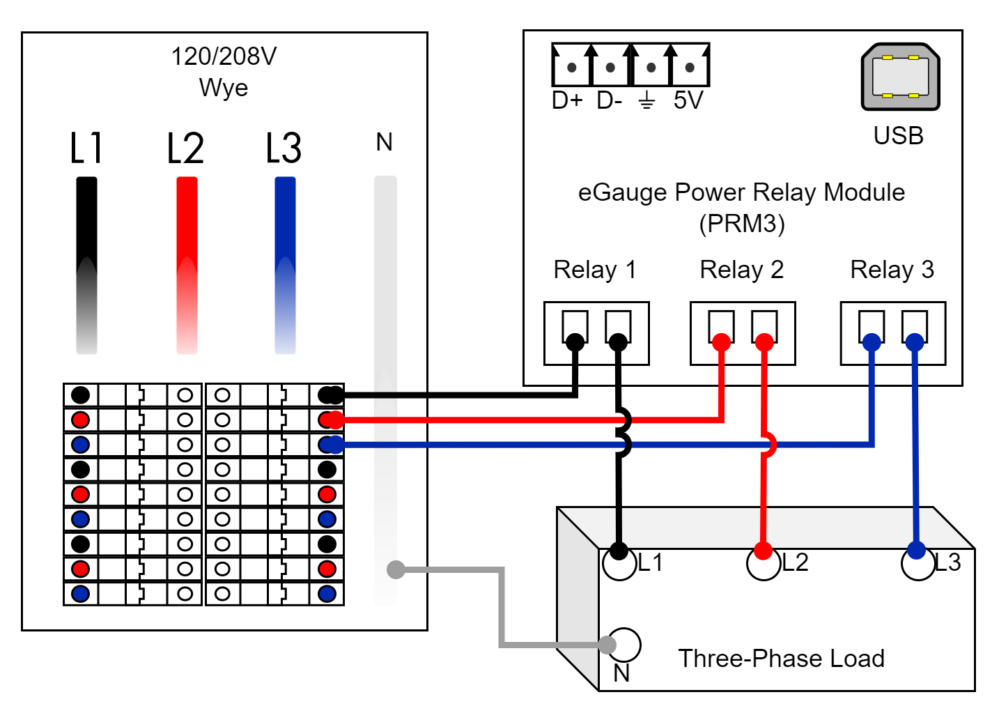](https://kb.egauge.net/uploads/images/gallery/2023-02/prm3-3ph-load.png) #### Single-phase load wiringNeutral may or may not be used depending on the load.
Be sure to control the two relay inputs simultaneously when turning on or off the single-phase load.
[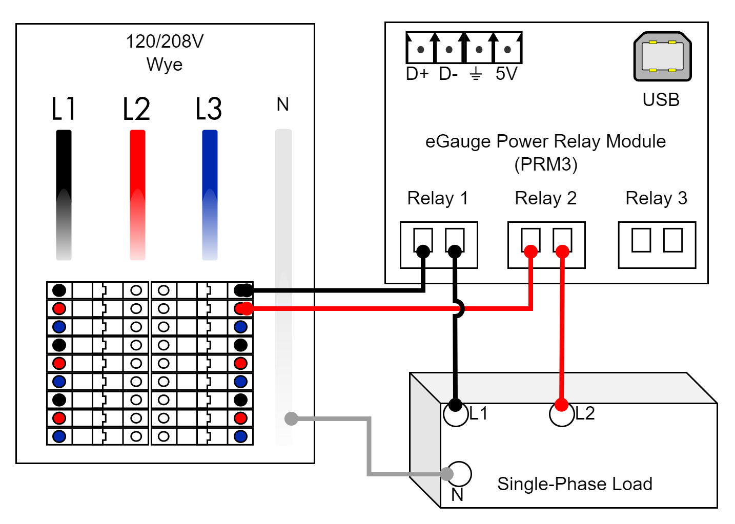](https://kb.egauge.net/uploads/images/gallery/2023-02/prm3-2ph-load.png) #### Split-phase load wiringNeutral may or may not be used depending on the load.
[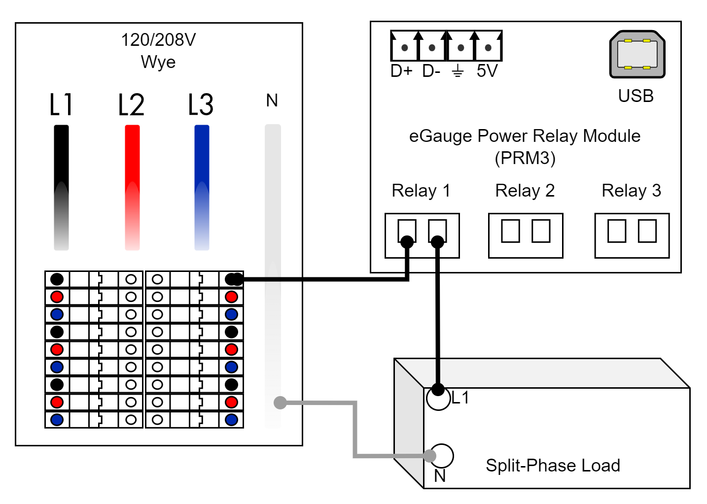](https://kb.egauge.net/uploads/images/gallery/2023-02/prm3-1ph-load.png) ## Related Material - [PRM3 software documentation](https://kb.egauge.net/books/other-hardware-documentation/chapter/power-relay-module-prm3-software-documentation) - [Lua Scripting](https://kb.egauge.net/books/advanced-egauge-operation/chapter/lua-scripting)