Other Accessories
Meter accessories sold by eGauge Systems.
- eGauge Display Caster
- 12 Volt Power Supply
- CT Extension Pack
- Step-down transformer
- Power Relay Module (PRM3)
eGauge Display Caster
Visit the online store page
Model: EDC
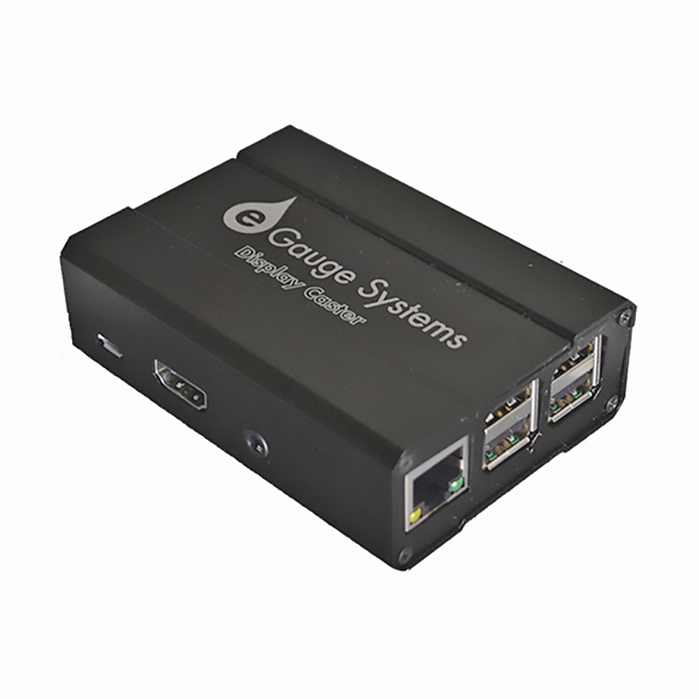 |
| eGauge Display Caster |
The eGauge Display Caster provides an easy method display an eGauge meter device interface on a TV or monitor via HDMI through an easy-to-use interface.
The Display Caster has a USB input for power, USB inputs for keyboard and mouse for initial configuration, and an HDMI output to connect to a TV or monitor. Network/internet connection can be obtained through built-in 2.4GHz WiFi or an Ethernet-direct connection.
Once the Display Caster is configured, the saved eGauge device interface will be displayed after automatically recovering from a power outage or communication loss.
Specifications
- USB-C powered*
- USB for keyboard and mouse
- Micro-HDMI to HDMI output*
- 2.4GHz b/g/n
* Versions shipped prior to 2023-08-18 are powered by Micro-USB and have a full-size HDMI port
Hardware included
- eGauge Display Caster
- USB-C to USB-A for power*
- 120V to USB-C power adapter for power*
- Micro-HDMI to HDMI cable*
- Printed Manual
- Velcro for mounting
* Versions shipped prior to 2023-08-18 include a Micro-USB to USB-A cable, 120V to Micro-USB adapter, and HDMI cable instead
Assembly/installation information
The default password for the display caster is printed on the paper attached to the manual, as well as inside the box with the eGauge Display Caster. The password can be changed during setup.
Do not leave keyboard/mouse, or USB ports accessible in public kiosk display
- Connect keyboard and mouse via USB
- Connect HDMI to television or monitor
- Apply power using the 120V supply adapter, or USB-to-USB cable
- Configure network, timezone, and device to display and save as default (see Display Caster Manual for software setup information).
Software configuration Information
- Ensure timezone is set correctly
- Ensure default kiosk is saved
Follow the Display Caster Manual for software setup.
Factory Reset
Connect a keyboard and enter the factory reset code for your version of the display caster. You may need to try multiple key combinations depending on when your display caster was purchased. There is no danger in entering a key combination for a different model.
Current model: ctrl+shift+f simultaneously.
Previous model: shift+escape, f, r, tab one at a time.
Legacy model: ctrl+shift+j simultaneously.
Documents
- Display Caster Manual (current version)
- Display Caster Manual (previous version)
- Display Caster Manual (old version)
12 Volt Power Supply
Visit the online store page
SKU: PSU12V
The 12 Volt Power supply is a standard power supply to convert 100-240VAC @ 0.5A (50/60Hz) to +12VDC @ 1A used to power the BF430 RS485-to-Ethernet adapter, CR-Magnetics DC CTs and other powered devices. May be used on 240VAC services with the appropriate adapter (not included).
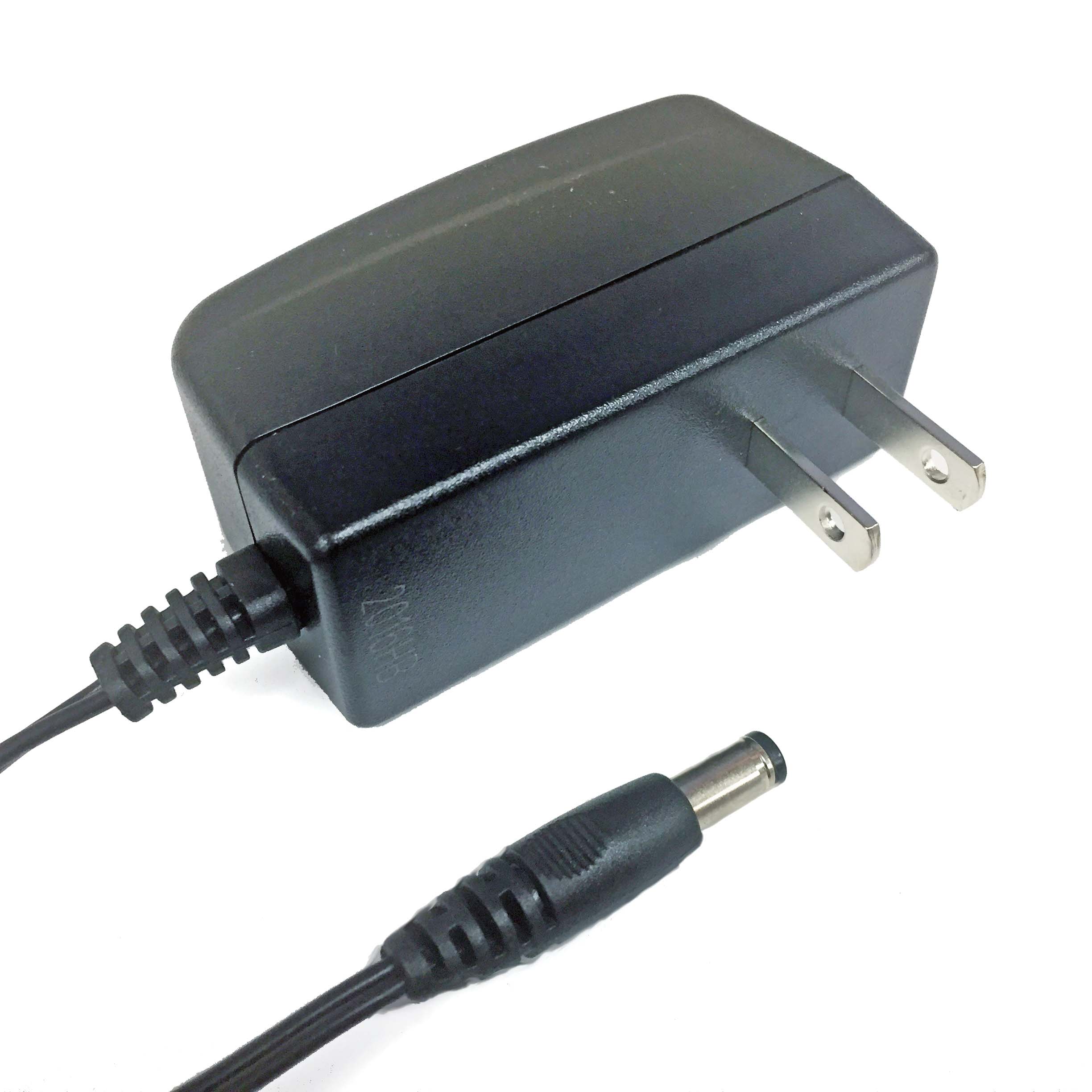 |
| 12V Power Supply |
Specifications
- 12Vdc output
- 120V US plug input
- Isolated supply
- barrel-jack connector
Hardware Included
- 2-prong US style power supply with barrel jack
Assembly/installation information
Can be used to supply power to:
- BF-430 RS485 to USB converter via barrel jack
- IMT irradiance sensor
- Other future product offerings by eGauge
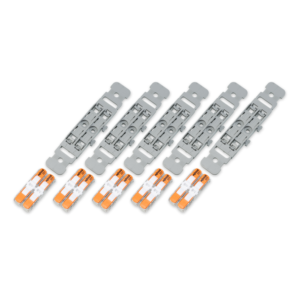
CT Extension Pack
Visit the online store page
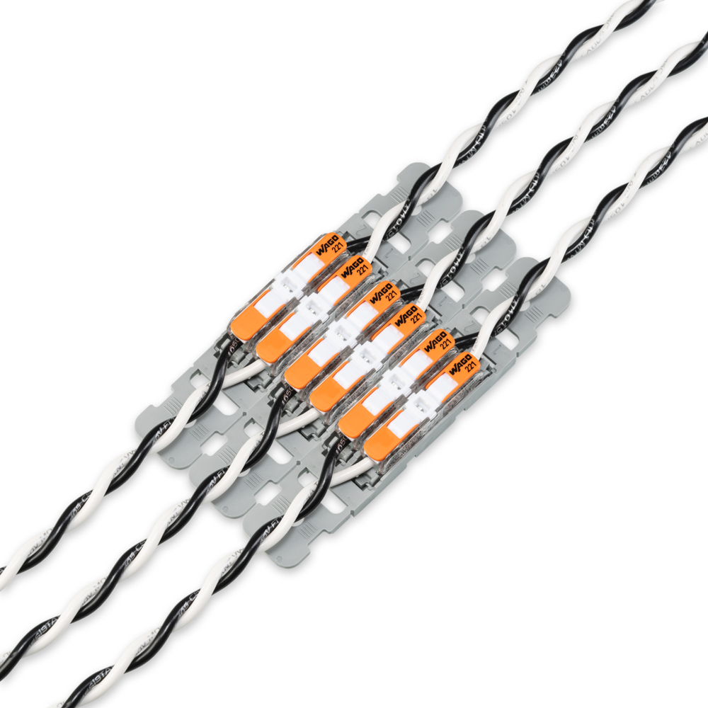
The eGauge CT Extension Pack can be used to extend CT leads in situations where soldering or butt-splice connections are not possible. CT leads should only be extended using twisted pair wiring and to a maximum recommended distance of 100 feet from the eGauge. For more details please see: Extending the Length of CT Leads
The eGauge CT Extension Kit is compatible with all eGauge meter models (eGauge2, EG30xx, EG4xxx)
Specifications
Full specs (data-sheet PDF)
- Convenient lever technology for easy tool-free connections
- Supports conductors from 20 to 12 AWG
- UL 600 V rated
- −30 °C – 70 °C (−22 °F – 158 °F)
- UL 486C
- EN 60998
OEM specification sheets:
Hardware included
One extension pack comes with enough connectors to extend 5 CT leads.
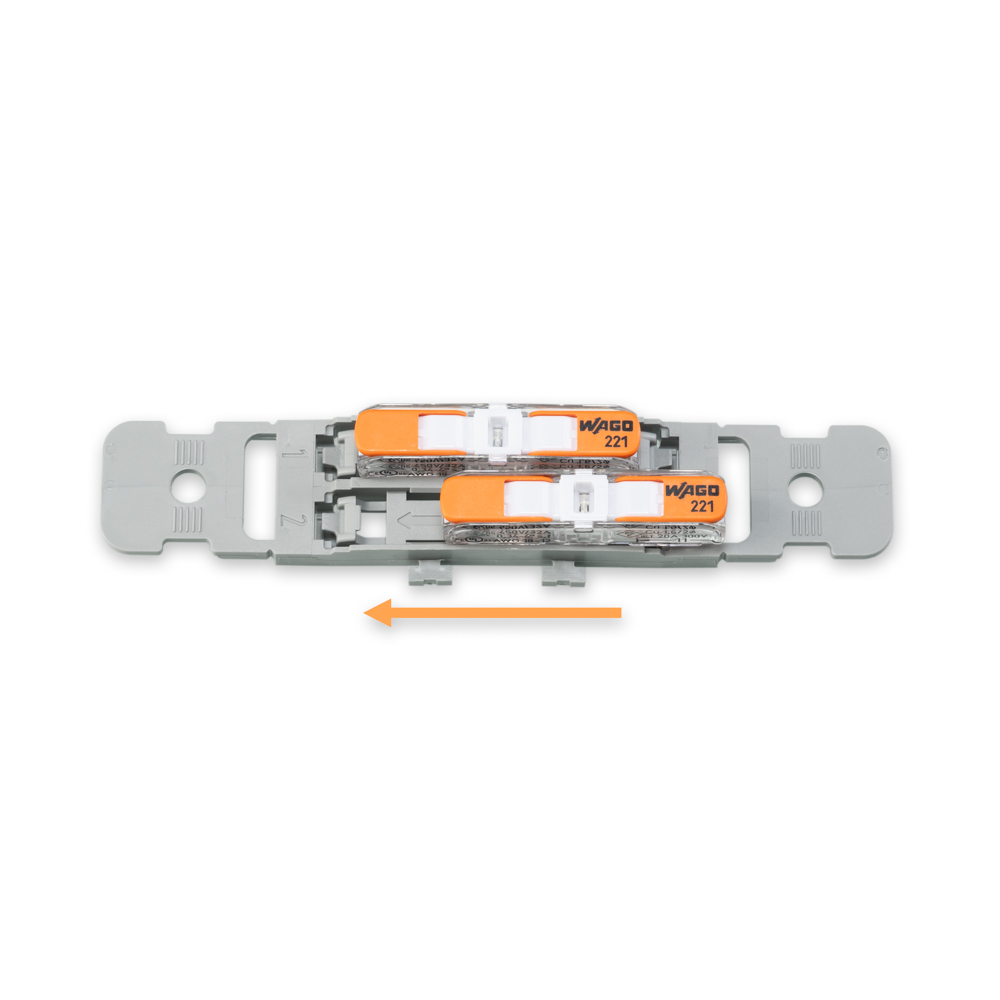
- 10x Wago 221-2401 Inline splicing connector with lever
- 5x Wago 221-2502 Mounting carrier with strain relief
Assembly/installation information
Slide the splicing connectors into the mounting carriers by inserting them behind the arrow and gently sliding forward until they click into place.
Remove the 2-pin connector from the CT lead and prep the lead to a strip length of 11mm/0.43". Insert one of the stripped wire ends into one end of an inline splicing connector.
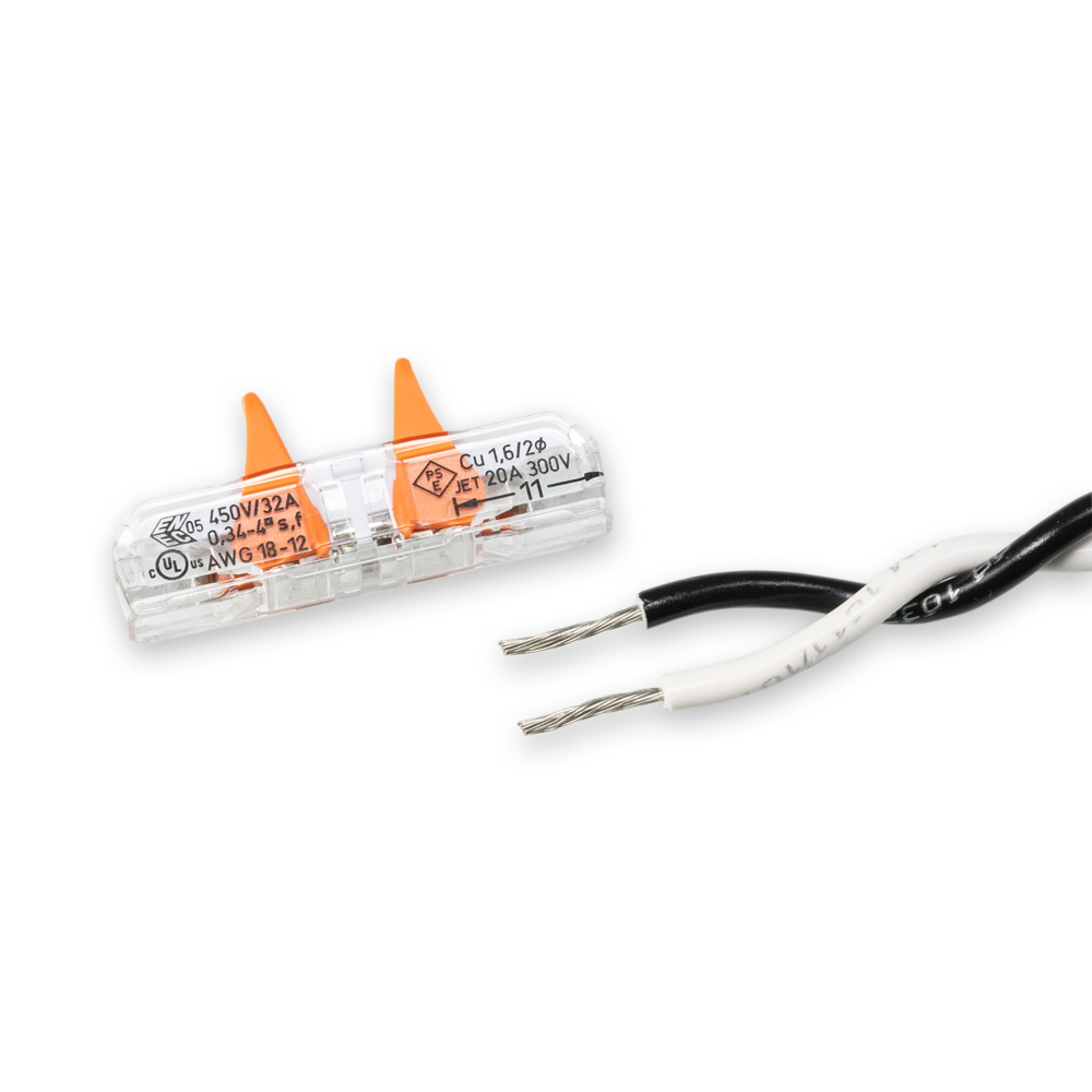
Lift the lever to insert the CT lead and lower the lever to secure the connection. You should use 1 inline connector per lead wire, using 2 inline connectors and 1 carrier to extend a single CT lead.
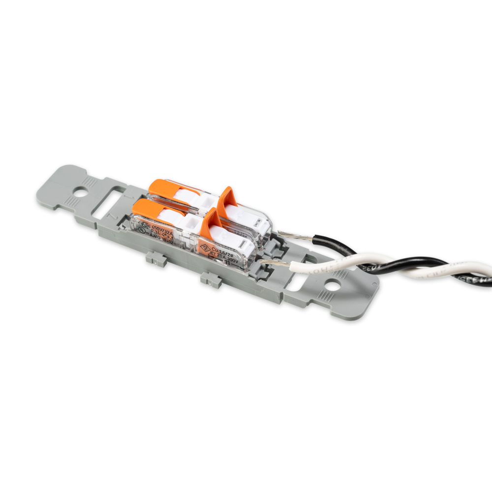
Strip the ends of the extension wiring to the appropriate length and connect to the other side of the inline splicing connectors in the same way. Be sure to line up black and white lead wires to the same inline connector.
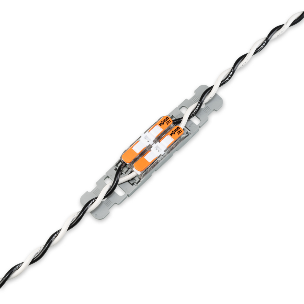
Attach the green 2-pin CT connector to the other end of the CT extension wiring and plug into the eGauge making sure to keep black and white wiring consistent throughout. Once assembled, give the wires a light pull to be certain that they're securely seated under the closed levers.
Multiple carriers can be connected together if needed using the side-by-side latches on the carriers. The carriers can be mounted or secured as desired.
Related Information
Step-down transformer
Visit the online store page
Current manufacturer information: Functional Devices model TR50VA008
Stepdown transformers are intended only to power 120V equipment off higher voltage service. To measure 480V delta systems (no neutral), 600V delta systems (no neutral), or 347/600V Wye, please use the EV1000 High Voltage Sensors.
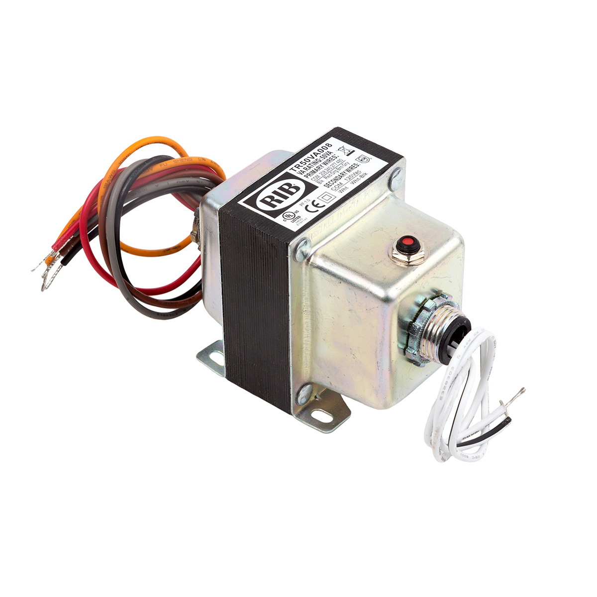 |
| Step-down transformer (480/277/240/208 to 120V) |
208/240/277/480V to 120Vac, dual hub, 50VA UL Listed transformer. Used for monitoring 480V delta services and powering 120V accessories from higher voltage systems.
Transformers provided by eGauge are 50VA (50 watts limit at 1.0 power factor, lower wattage when power factor < 1). They are intended to be used for powering a small amount of equipment provided by eGauge. Attempting to supply loads ~50VA or higher will cause the transformer to trip and require a manual reset.
Specifications
Full specs (data-sheet PDF)
- VA Rating: 50
- Frequency: 50/60 Hz
- Mounting: Foot & Dual Threaded Hubs
- Over Current Protection: Circuit Breaker
- Dimensions: 3.440 ̋ x 2.510 ̋ x 3.012 ̋ (w/ .500 ̋ NPT Hubs)
- Wire Length: 9.5 ̋ Typical w/ .5 ̋ Strip
- Operating Temperature: -30 to 140° F
- MTBF: 100,000 Hours @ 77° F
- Construction: Split-Bobbin
- Weight: 3.04 lbs.
- Approvals: UL5085-2 Listed General Purpose, US / Canada, CE, RoHS
Hardware included
- Step-down transformer
Assembly/installation information
Follow instructions included with transformer, ensure correct primary and secondary wires are used.
Documents
Related Information
- 277V Powered Enclosure Kit
- Potential Transformer Configuration
- Monitoring 480V and 600V systems
- EV1000 High Voltage Sensor
Power Relay Module (PRM3)
Visit the online store page
Model: PRM3
Polyphase equipment control danger warning
When controlling single-phase or three-phase loads that have more than one currently-carrying conductors (e.g., hot lines, not neutral or ground), be sure to control the relay inputs for the polyphase load simultaneously using mask controls, or there is risk of having the load operate without all phases which may cause damage to the equipment.
Read the PRM3 Owner's Manual for safety and full control information.
For control: requires eGauge Core or Pro, or a third party controller that supports Modbus RTU or SCPI.
By default, the PRM3 is configured with a 10-second minimum open/close duration to minimize unintentional wear on the relays or rapid load switching. For example, by default when a relay input is opened, it will remain in the open state for at least 10 seconds before a command to close it will be acknowledged. This minimum delay may be reconfigured between 0 seconds and 4 minutes and 15 seconds using Modbus or SCPI commands.
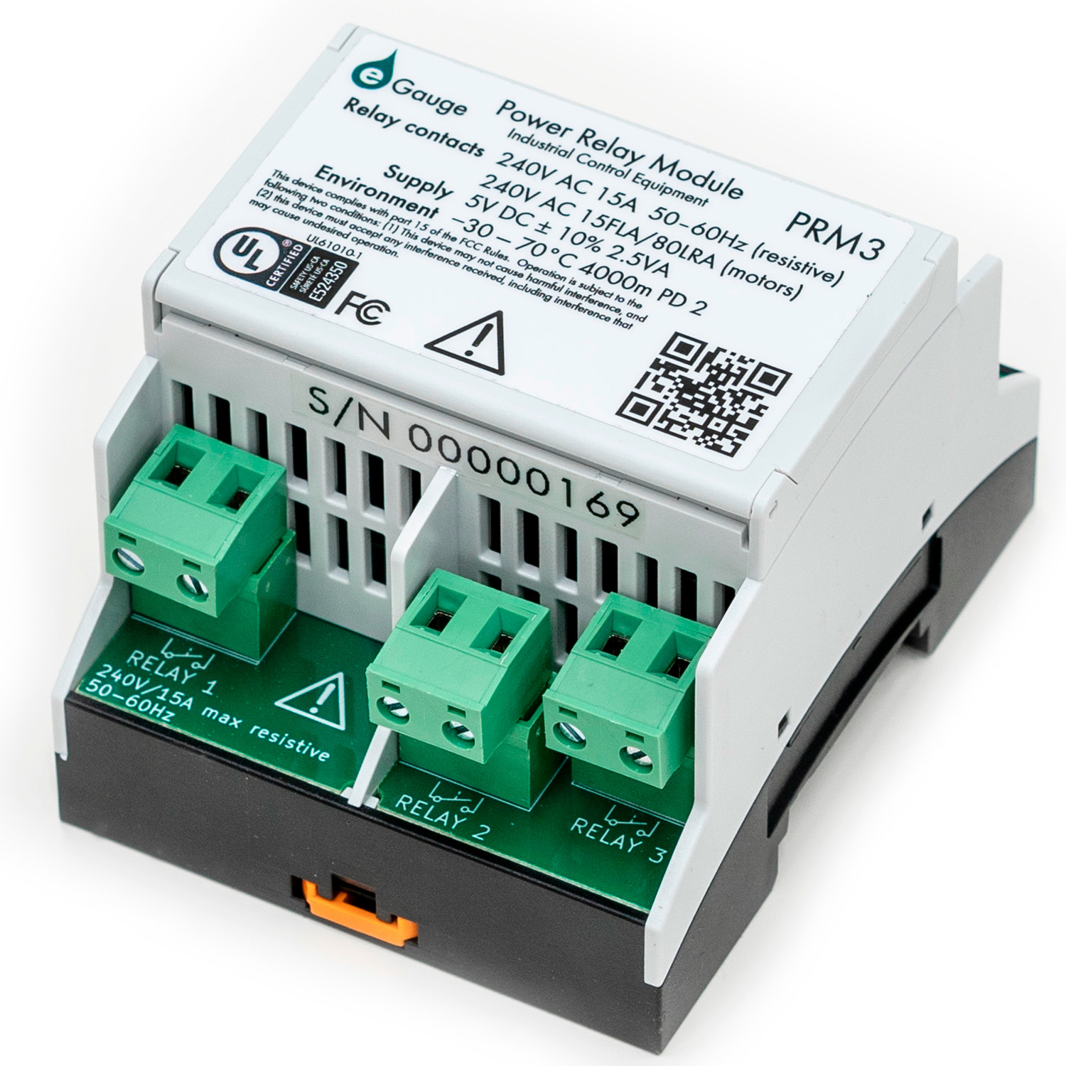
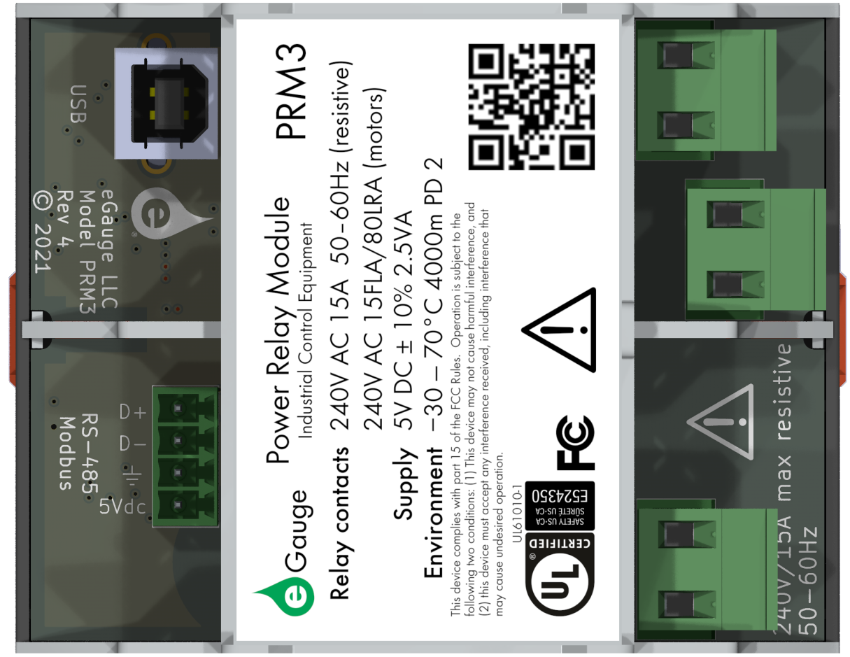
The eGauge Power Relay Module is a versatile device intended to control up to three 240V AC/15 A resistive loads or motors up to 15 FLA (80 LRA). The relays can be opened and closed individually or synchronously, enabling the switching of up to three single-phase loads, one split-phase and one single-phase load, or one three-phase load.
Intended applications include Remote control of air conditioners, heaters, refrigerators, office-automation, and similar equipment.
 |
 |
| "Front" of PRM3 with relay contacts |
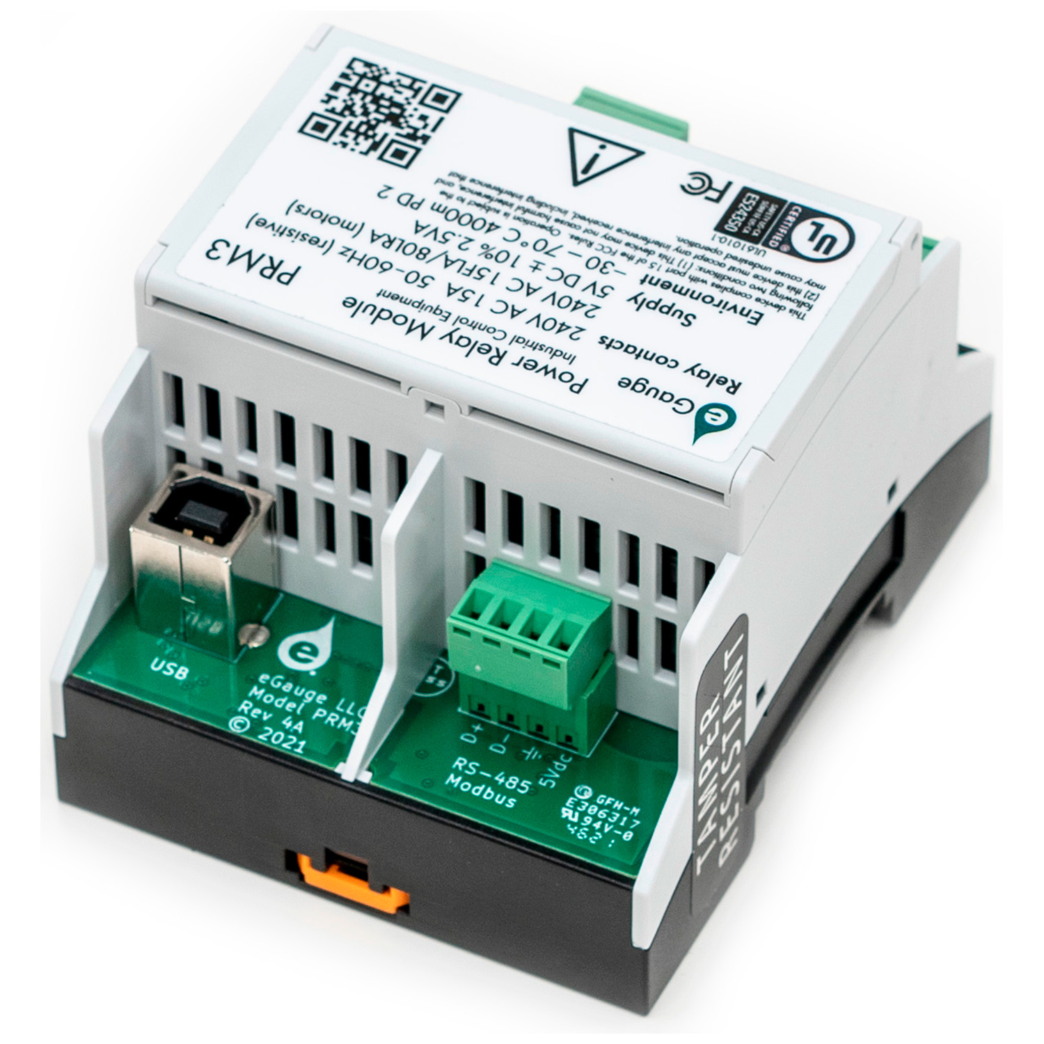
"Back" of PRM3 with USB and RS485 for power and communication |
Specifications
Full specs (data-sheet PDF)
- Contacts rated for up to 240 V AC/15 A resistive (50-60 Hz)
- Relay state persists across power-outages
- Normally open contacts
- Can be switched independently or in arbitrary groups
- Configurable minimum open/close duration to minimize relay wear
- DIN-rail enclosure
- USB interface
- Easy to use SCPI command set (text commands)
- USB powered
- RS-485 Interface
- Single 5 V DC/500 mA power supply
- Modbus protocol
- SunSpec compatible
- Low average power consumption
- <500 mW typical with all relays on
- <100 mW with relays off
- Wide operating range: -30. . . 70 ◦ C, up to 4000 m altitude
- Certifications
- UL Listed: IEC/UL 61010-1 Ed. 3.0 B:2010, File Number E524350
- FCC
- FCC’s Title 47 CFR Part 15 Subpart B Class B
- ICES-003 Information Technology Equipment Class
- 2-year Limited Warranty
Hardware included
- 1x eGauge PRM3 power relay module
- 6' USB Type-A to USB Type-B cable for meter or SCPI control and power
- 3x 2-pin terminal blocks for relays
- 1x 4-pin terminal block for RS-485 connection for Modbus and power
Assembly/installation information
The Power Relay Module is usually installed near the load (or loads) that it controls. It is permanently connected equipment.
The Power Relay Module is a listed device and must be installed inside a suitable enclosure. The enclosure must be rated according to the environment it is used in. For example, outdoor installations require an outdoor-rated enclosure such as
IPX4/NEMA4.
- Connect the source and load hot wires to each applicable relay port (neutral, if applicable, is always left connected directly to the load).
- A three-phase load will use all 3 relay inputs.
- A single-phase load (2 hots) will use 2 relay inputs.
- A split-phase (hot and neutral) will use one relay input.
- Connect the USB port and/or RS-485 communication port to the controller or building automation system.
- If using using the eGauge meter to control the relay, connect the relay's USB port to an eGauge meter USB port.
- If using SCPI control with a third party controller, connect the relay's USB port to the a controller USB port.
- If using Modbus control with a third party controller, wire the D+, D-, and Ground pins of the relay's 4-pin plug to the controller's RS485 line. Power is provided via the +5V and Ground pins on the 4-pin plug, or by connecting the relay USB port to another host.
- If using using the eGauge meter to control the relay, connect the relay's USB port to an eGauge meter USB port.
- When controlling polyphase loads with multiple relay inputs, open and close the relays simultaneously (such as with masks) to avoid damage to the equipment.
Software Configuration
Be sure to use mask commands for controlling polyphase loads that use multiple PRM3 contacts!
The eGauge PRM3 may be controlled through several different options:
- eGauge Meter Interactive Dashboard control
- eGauge Meter Lua Scripting
- eGauge Meter JSON WebAPI control
- Modbus RTU (RS-485 Serial)
- SCPI (USB via a CDC ACM virtual serial port)
Documents
Related Information
Diagrams
PRM3 overview
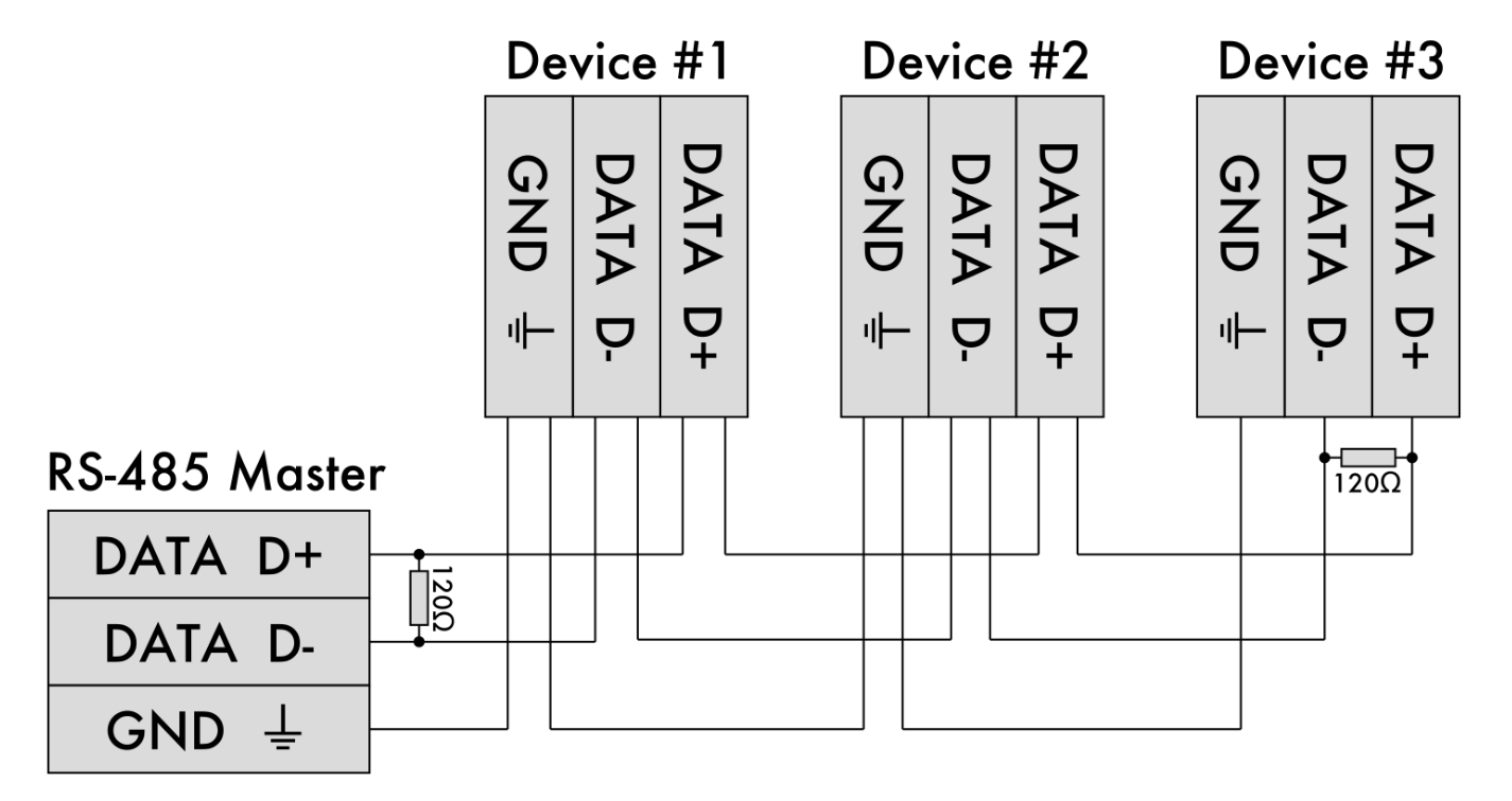
Typical RS-485 Wiring Example
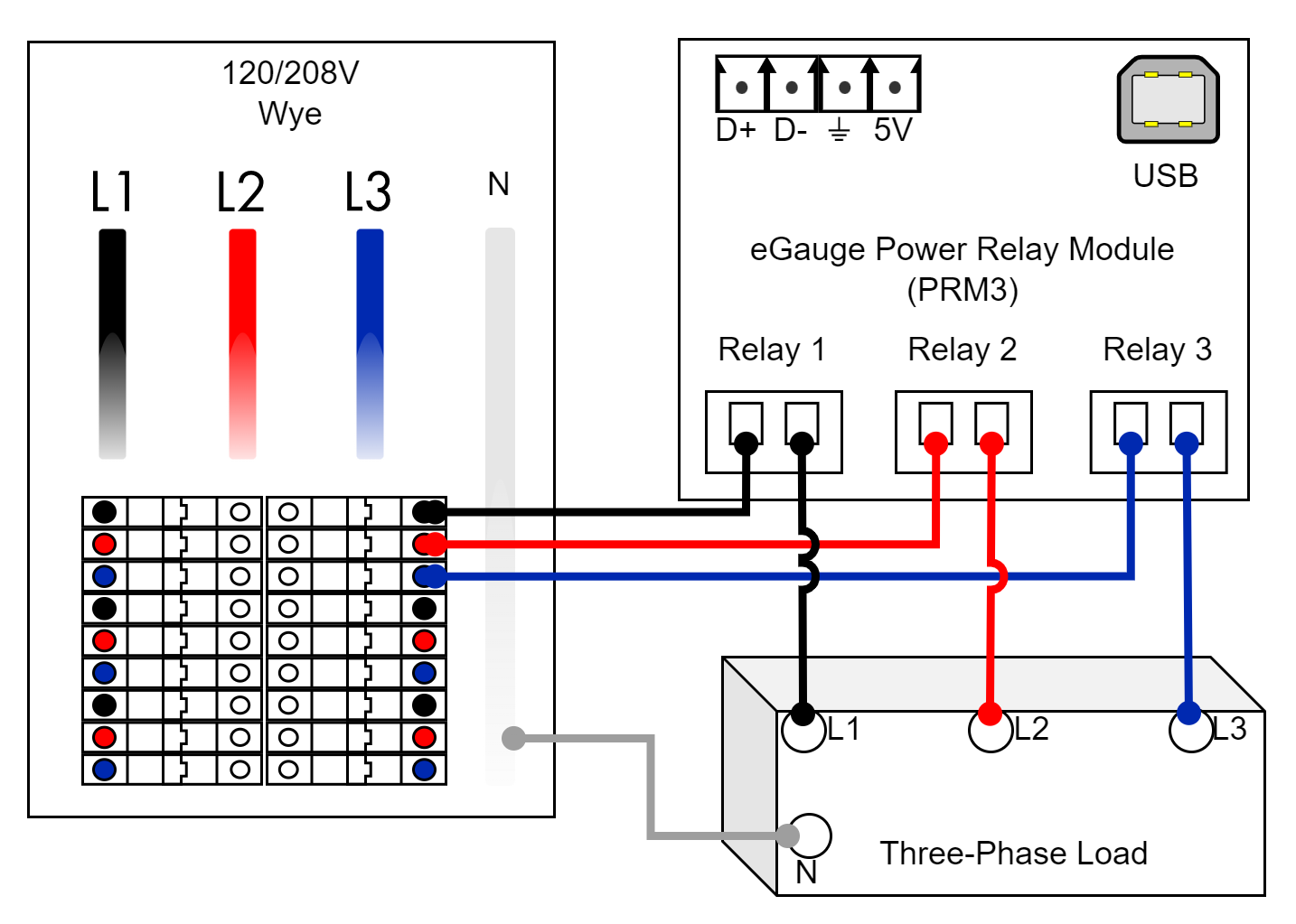
3-phase load wiring
Neutral may or may not be used depending on the load.
Be sure to control all 3 relay inputs simultaneously when turning on or off the three-phase load.
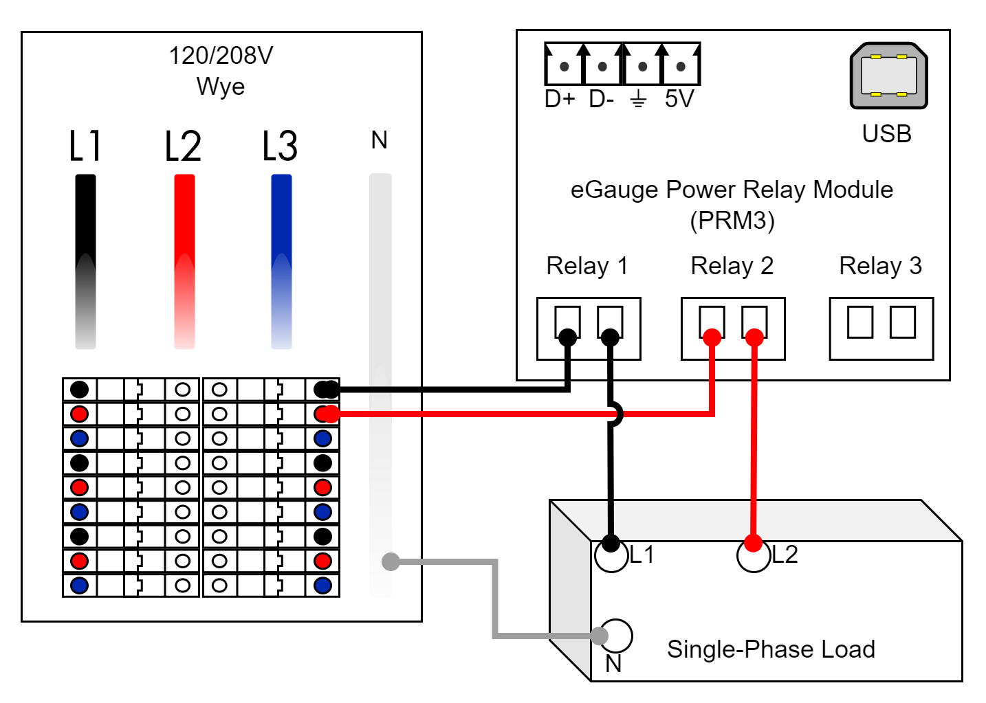
Single-phase load wiring
Neutral may or may not be used depending on the load.
Be sure to control the two relay inputs simultaneously when turning on or off the single-phase load.
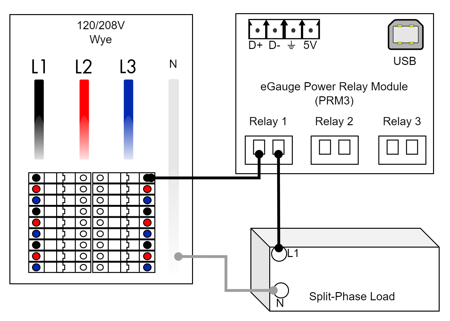
Split-phase load wiring
Neutral may or may not be used depending on the load.