Requires the [**eGauge Sensor Hub**](https://kb.egauge.net/books/egauge-hardware-product-pages/page/sensor-hub-%28esh044%29 "eGauge Sensor Hub") and eGauge model EG4xxx (Pro or Core), not compatible with older model units.
Only use straight-through RJ-11 cables to connect powered sensors to the Sensor Hub. Telephone systems generally use "reverse" style RJ-11 cables which are incompatible with the Sensor Hub. See **[this article](https://kb.egauge.net/books/egauge-installation/page/rj-11-wiring-between-sensor-hub-and-sensors)** for more information on verifying the correct RJ-11 wiring. Every Sensor Hub compatible sensor sold by eGauge Systems comes with a straight-through RJ-11 cable.
The eGauge Pulse Sensor is used in conjunction with the [Sensor Hub](https://kb.egauge.net/books/sensors/page/sensor-hub-%28esh044%29) and an EG4xxx model meter (Core or Pro) to record pulse output data from devices such as water and gas meters. The Pulse Sensor can accept standard 2-wire pulse outputs or 3-wire 5-volt Hall effect pulse outputs. [See our Sensors product introduction video here](https://www.youtube.com/watch?v=6D82guIQP50&feature=youtu.be).| [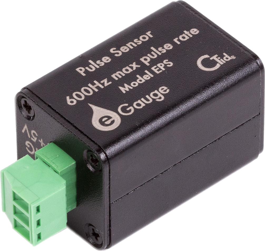](https://kb.egauge.net/uploads/images/gallery/2020-02/pulse-sensor-1006x951-transparent.png) | [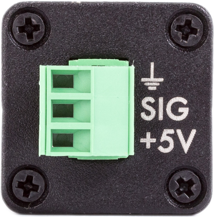](https://kb.egauge.net/uploads/images/gallery/2020-02/pulse-topdown.png) | [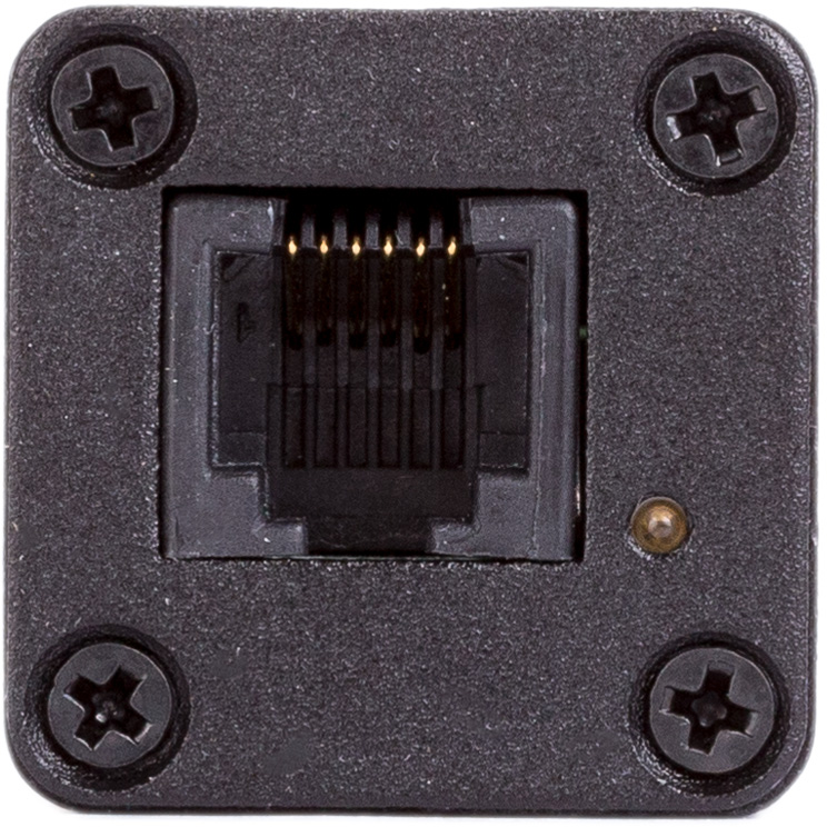](https://kb.egauge.net/uploads/images/gallery/2020-02/sensor-rj11.png) |
| *Side view of EPS* | *Front view of EPS with connections* | *Back-side of EPS with RJ-11 port and CTid locator LED* |
Requires the [**eGauge Sensor Hub**](https://kb.egauge.net/books/egauge-hardware-product-pages/page/sensor-hub-%28esh044%29 "eGauge Sensor Hub") and eGauge model EG4xxx (Pro or Core), not compatible with older model units.
Analog sensors require ≤ 50Ω output.
Only use straight-through RJ-11 cables to connect powered sensors to the Sensor Hub. Telephone systems generally use "reverse" style RJ-11 cables which are incompatible with the Sensor Hub. See **[this article](https://kb.egauge.net/books/egauge-installation/page/rj-11-wiring-between-sensor-hub-and-sensors)** for more information on verifying the correct RJ-11 wiring. Every Sensor Hub compatible sensor sold by eGauge Systems comes with a straight-through RJ-11 cable.
The eGauge 2V Analog Input is used in conjunction with the [Sensor Hub](https://kb.egauge.net/books/sensors/page/sensor-hub-%28esh044%29) and an EG4xxx model meter (Core or Pro) which allows EG4xxx meters to read 0 -- 2V low-impedance analog values or states from standard 2-wire dry contacts such as relays. [See our Sensors product introduction video here](https://www.youtube.com/watch?v=6D82guIQP50&feature=youtu.be).| [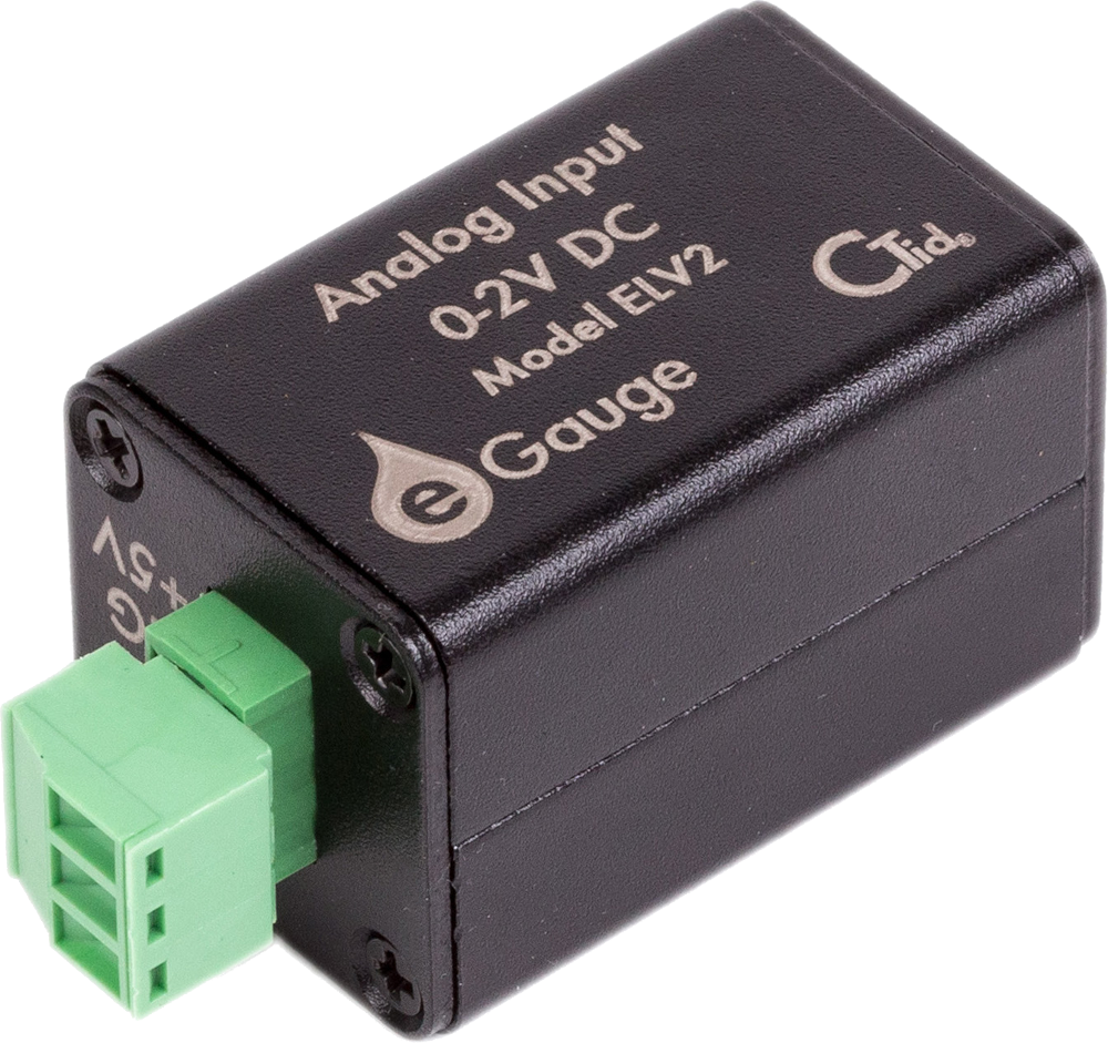](https://kb.egauge.net/uploads/images/gallery/2020-02/2v-sensor-1000x941-transparent.png) | [](https://kb.egauge.net/uploads/images/gallery/2020-02/pulse-topdown.png) | [](https://kb.egauge.net/uploads/images/gallery/2020-02/sensor-rj11.png) |
| *Side view of ELV2* | *Front view of ELV2 with connections* | *Back-side of ELV2 with RJ-11 port and CTid locator LED* |
Requires the [**eGauge Sensor Hub**](https://kb.egauge.net/books/egauge-hardware-product-pages/page/sensor-hub-%28esh044%29 "eGauge Sensor Hub") and eGauge model EG4xxx (Pro or Core), not compatible with older model units.
When monitoring input/output temperatures, it is best to purchase multiple probes in the same order for highest accuracy.
Only use straight-through RJ-11 cables to connect powered sensors to the Sensor Hub. Telephone systems generally use "reverse" style RJ-11 cables which are incompatible with the Sensor Hub. See **[this article](https://kb.egauge.net/books/egauge-installation/page/rj-11-wiring-between-sensor-hub-and-sensors)** for more information on verifying the correct RJ-11 wiring. Every Sensor Hub compatible sensor sold by eGauge Systems comes with a straight-through RJ-11 cable.
The eGauge Temperature Probe Sensor is used in conjunction with the [Sensor Hub](https://kb.egauge.net/books/sensors/page/sensor-hub-%28esh044%29) and an EG4xxx model meter (Core or Pro) to to log temperature data. The Temperature Probe Sensor is used for precision fluid temperature measurement (through thermowell) and precision ambient temperature measurement from 0 °C to 100 °C. For ambient temperature monitoring, see the [Ambient Temperature Sensor (ETLW)](https://kb.egauge.net/books/sensors/page/ambient-temp-sensor-%28etlw%29 "Ambient Temp Sensor (ETLW)"). [See our Sensors product introduction video here](https://www.youtube.com/watch?v=6D82guIQP50&feature=youtu.be).| [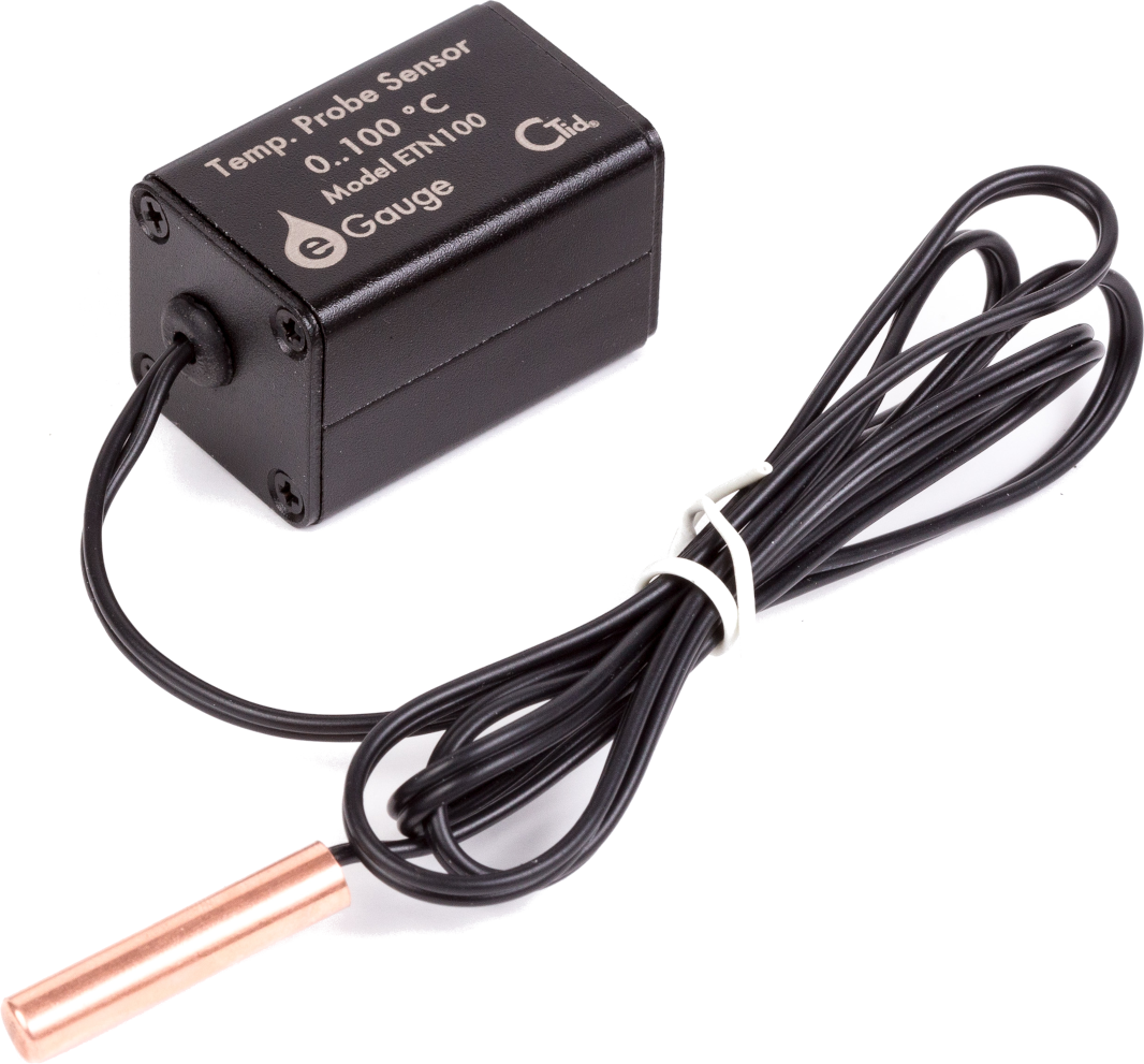](https://kb.egauge.net/uploads/images/gallery/2020-02/probe-temp-sensor-withprobe-1066x991-transparent.png) | [](https://kb.egauge.net/uploads/images/gallery/2020-02/sensor-rj11.png) |
| *Side view of ETN100 and probe* | *Back-side of ETN100 with RJ-11 port and CTid locator LED* |
Requires the [**eGauge Sensor Hub**](https://kb.egauge.net/books/egauge-hardware-product-pages/page/sensor-hub-%28esh044%29 "eGauge Sensor Hub") and eGauge model EG4xxx (Pro or Core), not compatible with older model units.
Only use straight-through RJ-11 cables to connect powered sensors to the Sensor Hub. Telephone systems generally use "reverse" style RJ-11 cables which are incompatible with the Sensor Hub. See **[this article](https://kb.egauge.net/books/egauge-installation/page/rj-11-wiring-between-sensor-hub-and-sensors)** for more information on verifying the correct RJ-11 wiring. Every Sensor Hub compatible sensor sold by eGauge Systems comes with a straight-through RJ-11 cable.
The eGauge Ambient Temperature Sensor (ETLW) is used in conjunction with the [Sensor Hub](https://kb.egauge.net/books/sensors/page/sensor-hub-%28esh044%29) and an EG4xxx model meter (Core or Pro) to record temperature data from systems such as HVAC systems, cold storage, data centers and other controlled environments. For fluid temperature monitoring, see the [Temperature Probe Sensor (ETN100)](https://kb.egauge.net/books/sensors/page/temperature-probe-sensor-%28etn100%29 "Temperature Probe Sensor (ETN100)"). [See our Sensors product introduction video here](https://www.youtube.com/watch?v=6D82guIQP50&feature=youtu.be).| [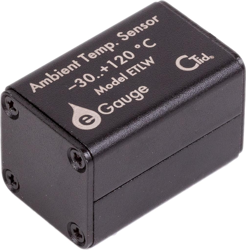](https://kb.egauge.net/uploads/images/gallery/2020-02/image-1582305297233.png) | [](https://kb.egauge.net/uploads/images/gallery/2020-02/sensor-rj11.png) |
| *Side view of ETLW* | *Back-side of ETLW with RJ-11 port and CTid locator LED* |
If using multiple IMT weather stations on the same serial bus, the Modbus address must be changed. See the manufacturer's information at [https://www.imt-solar.com/downloads/](https://www.imt-solar.com/downloads/) under "Software Si-Series" for more information.
If splicing into a "wall wart" style DC power supply wires, verify the polarity of the DC output is correct with a voltmeter. Typically, **the wire with a white stripe or dash** is the **positive** line.
### OEM Data Sheets Visit [https://www.imt-solar.com/](https://www.imt-solar.com/) . Additional or newer version documents may be found in the "Downloads" section. - [Irradiance Sensor Main Unit Reference Guide (required for accessories)](https://www.imt-solar.com/fileadmin/docs/en/products/Si_Instruction-digital_202205_EN.pdf) - [Irradiance Sensor Main Unit Data Sheet](https://www.imt-solar.com/fileadmin/docs/en/products/Si-Sensor_202205_E.pdf) - [Wind Speed Sensor Data Sheet](https://www.imt-solar.com/fileadmin/docs/en/products/Vwind-Si_E.pdf) - [Ambient Temperature Sensor Data Sheet](http://www.imt-solar.com/fileadmin/docs/en/products/Tamb-Si_E.pdf) ### Hardware Included - IMT Weather Station (Si-RS485TC-2T-v-MB) - Barrel connector to screw terminal block set - 12Vdc power supply (120V American outlet wall-wart style) ### Installation and Wiring For best results, the IMT sensor must be installed in the same plane as the solar array. The sensor window should be clean and clear of any obstructions. Follow the mounting instructions included with the IMT sensor, and [contact IMT directly](https://imtsolar.com/contact/) with any questions regarding unique installation environments. The IMT sensor has four wires and a heavier gauge wire shield connector. Depending on the application, the wire shield may or may not be used, and it is not shown in the following diagrams. If required, the wire shield should be connected to **earth ground**, not the RS485 ground or signal ground. Note that proper wiring is *essential*. Failure to wire the IMT sensor correctly will prevent the sensor from functioning and may cause damage. --- ##### Wiring for EG4xxx with RS485-USB adapter The following diagram shows the IMT sensor connected to a 12Vdc power supply and RS485-USB adapter. The eGauge is not shown.If splicing into a "wall wart" style DC power supply wires, verify the polarity of the DC output is correct with a voltmeter. Typically, **the wire with a white stripe or dash** is the **positive** line.
[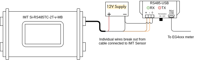](https://kb.egauge.net/uploads/images/gallery/2021-04/image-1619628467279.png) The wire assignments are as follows: Black: Negative side of 12Vdc power supply Red: Positive side of 12Vdc power supply Orange: D- terminal on RS485-USB adapter Brown: D+ terminal on RS485-USB adapterThe larger, thick black wire is a grounded shield and must not be connected to the eGauge, power supply or USB485 converter. Only connect this wire if you know what you are doing as improper grounding conditions can cause damage or communication issues.
Additionally, it is necessary to connect the ground (⏚) terminal on the RS485-USB adapter to the negative terminal of the 12Vdc power supply. A barrel connector with terminal blocks is included with the IMT sensor. Use the female side to quickly connect the IMT sensor to the 12Vdc power supply without splicing any wires. The male side can be discarded or saved for use in another project. [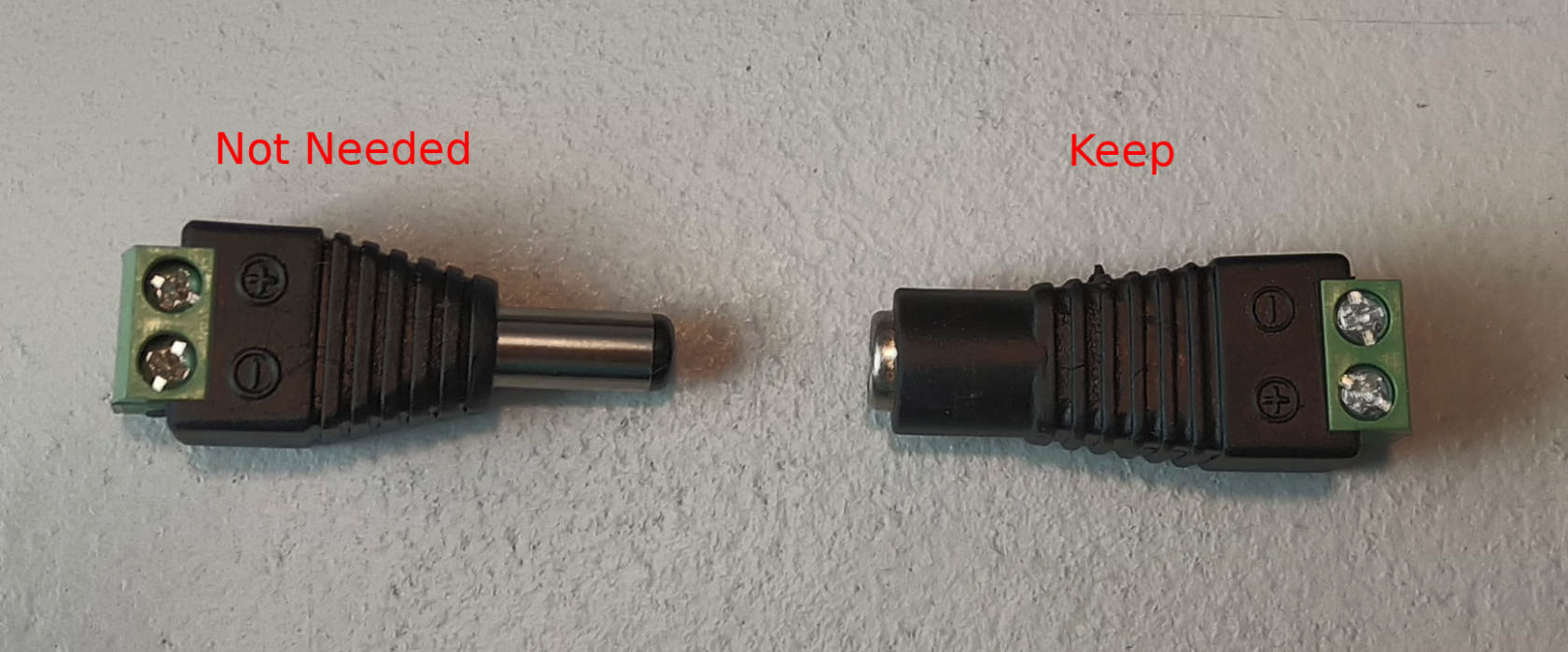](https://kb.egauge.net/uploads/images/gallery/2021-04/image-1619628932764.png) Use the included USB cable to connect the RS485-USB adapter to the eGauge, and make a note of which port is used (USB1 or USB2). Also ensure the termination switch on the RS485-USB adapter is set to "ON". --- ##### Wiring for EG30xx using BF430 serial to Ethernet adapter The following diagram shows the IMT sensor connected to a BF430 serial to Ethernet adapter. The eGauge is not shown. [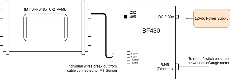](https://kb.egauge.net/uploads/images/gallery/2021-04/image-1619630594867.png) The wire assignments are as follows: Black: 9-30V- Red: 9-30V+ Orange: RS485- terminal on BF430 adapter Brown: RS485+ terminal on BF430 adapter A note on power: The BF430 obtains power through a 9-30Vdc power supply, and can optionally share that power source with a connected device. As such, all four wires on the IMT sensor are connected to the BF430. However, note that the 12Vdc power supply provided by eGauge (or a similar 12Vdc power supply) should be used, as 9Vdc is too low for the IMT sensor. A barrel connector with terminal blocks is included with the IMT sensor, but it is not needed for this application. Discard this piece, or save it for another project. [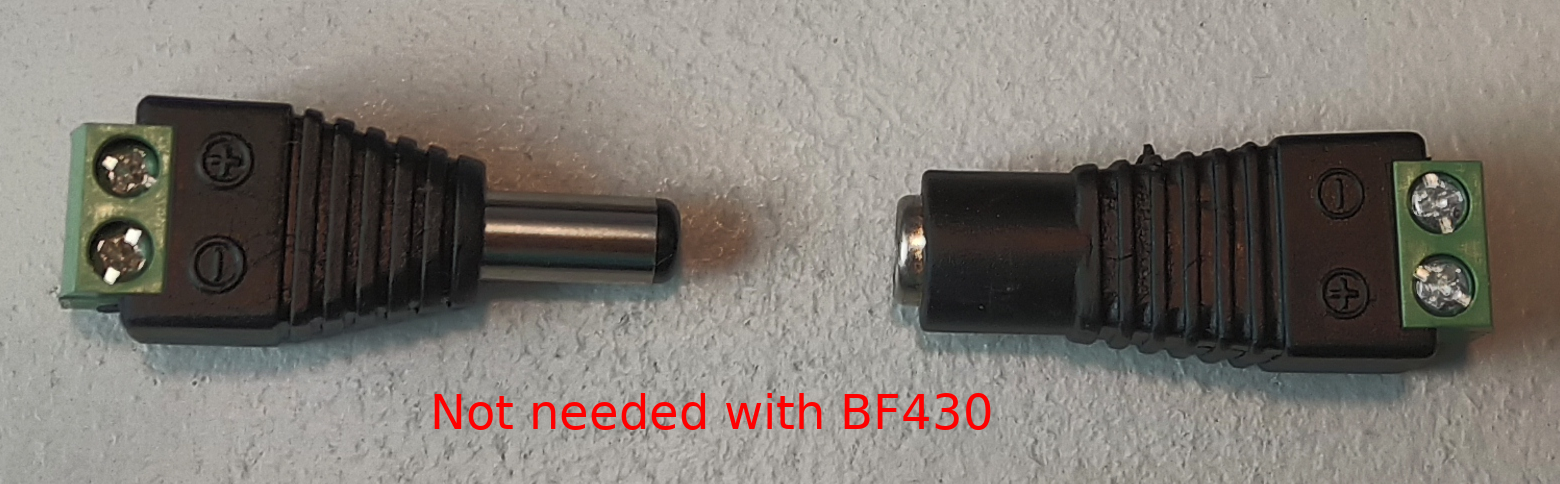](https://kb.egauge.net/uploads/images/gallery/2021-04/image-1619630478825.png) Connect the BF430 to the same local area network as the eGauge, and ensure the external switch is set to "485". --- ### Configuration As a supported device, the IMT sensor has a predefined map built into the eGauge meter. This makes addressing and configuration very simple when using a RS485-USB adapter. Configuration with a BF430 is significantly more complex.Valid credentials are required for the eGauge meter in order to make changes. See [this article](https://kb.egauge.net/books/configuration/page/what-password-do-i-use-to-save-a-change-to-the-settings) for more information.
##### Configuration for EG4xxx using RS485-USB adapter The RS485-USB adapter does not require any configuration on the adapter side. However, it's important to note which USB port is in use by the adapter. It's also necessary to ensure the termination switch is set to "on" when used with the IMT sensor. 1\. Navigate to **Settings -> Installation**. 2\. Under the "Remote Devices" section, click "Add Device" to add a new remote device. 3\. Enter a suitable device name. This field is arbitrary, but should make sense to the end user. 4\. Click the "Edit" button, and set the protocol to "Serial" 5\. Enter the device address. This will be `modbus://imt_si.1@USBX` where X is the USB port (1 or 2). [](https://kb.egauge.net/uploads/images/gallery/2021-04/image-1619631310826.png) 6\. Click the grey "?" next to the device address field. After a few seconds, this should turn into a green check mark. 7\. To save these settings, click the "Save" button at the bottom of the page.If a red X appears instead of a green check mark, ensure the wiring is correct, the USB port is identified correctly, the address is entered correctly, and that the IMT sensor has power.
Assuming a green check mark is displayed, the next step is to configure the eGauge to store data from the IMT sensor. To do this, at least one register will need to be created. 1\. Ensure a green check mark is shown next to the remote device address. If a grey "?" is shown, click it and wait for it to turn into a green check mark. 2\. On the Installation page, navigate to the "Registers" section and click "Add Register". 3\. Enter a suitable register name. This field is arbitrary, but should make sense to the end user. 4\. The default register type will be set to "P". Click the dropdown menu and select the remote device name for the IMT sensor. 5\. A second dropdown menu will appear. Select the remote register to record. [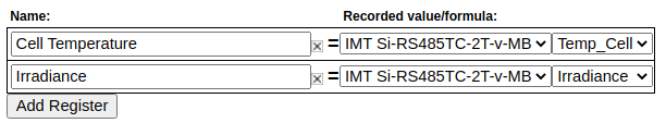](https://kb.egauge.net/uploads/images/gallery/2021-04/image-1619631800730.png) 6\. Repeat steps 2-5 for each remote register. 7\. To save these settings, click the "Save" button at the bottom of the page. The meter will reboot. 8\. Once the meter reboots, the RX and TX LEDs on the RS485-USB adapter should be blinking.The IMT sensor has add-on hardware to measure ambient temperature and windspeed. These registers will be listed even if that hardware is not connected, but they will return invalid values if selected
--- ##### Configuration for EG30xx with BF430 serial to Ethernet adapter The BF430 requires additional configuration through its internal web interface. A computer with an Ethernet port and an Ethernet cable are required for configuration. The two primary areas of concern are applying the correct serial settings (listed below) and setting the BF430 to use either a dynamic IP address (obtained with DHCP) or a static IP address. Refer to the [BF430 manual](https://www.egauge.net/media/support/docs/BF430_manual.pdf) for additional information.Support for the BF430 is limited. Using a RS485 to USB adapter is *strongly* recommended.
1\. Ensure the BF430 is configured to use the following serial settings for RS485 communication: 9600 baud, 8 data bits, no parity, 1 stop bit. 2\. Ensure the BF430 is set to obtain an IP address via DHCP or use an appropriate static IP address depending on the network requirements (generally, DHCP is preferred). Once the BF430 has been configured and wired: 1\. Navigate to **Settings -> Installation**. 2\. Under the "Remote Devices" section, click "Add Deice" to add a new remote device. 3\. Enter a suitable device name. This field is arbitrary, but should make sense to the end user. 4\. Click the "Edit" button, and set the protocol to "Serial" 5\. Enter the device address. This will be `modbus://imt_si.1@MAC` where MAC is the MAC address of the BF430. If the BF-430 has been configured with a *static IP*, the IP may be used instead. [](https://kb.egauge.net/uploads/images/gallery/2021-04/image-1619639722258.png) 6\. Click the grey "?" next to the device address field. After a few seconds, this should turn into a green check mark. 7\. To save these settings, click the "Save" button at the bottom of the page.If a red X appears instead of a green check mark, ensure the wiring is correct, the USB port is identified correctly, the address is entered correctly, and that the IMT sensor has power.
Assuming a green check mark is displayed, the next step is to configure the eGauge to store data from the IMT sensor. To do this, at least one register will need to be created. 1\. Ensure a green check mark is shown next to the remote device address. If a grey "?" is shown, click it and wait for it to turn into a green check mark. 2\. On the Installation page, navigate to the "Registers" section and click "Add Register". 3\. Enter a suitable register name. This field is arbitrary, but should make sense to the end user. 4\. The default register type will be set to "P". Click the dropdown menu and select the remote device name for the IMT sensor. 5\. A second dropdown menu will appear. Select the remote register to record. [](https://kb.egauge.net/uploads/images/gallery/2021-04/image-1619631800730.png) 6\. Repeat steps 2-5 for each remote register. 7\. To save these settings, click the "Save" button at the bottom of the page. The meter will reboot. 8\. Once the meter reboots, the RX and TX LEDs on the BF430 adapter should be blinking. --- ### Viewing Data The data recorded from the IMT sensor can be viewed like any other data point recorded by the meter. To see this data, navigate to the main graph page and select the appropriate register(s) from the list under the main graph. In the following example, the graph is set to display irradiance data (with temperature and windspeed data as options under the main graph. [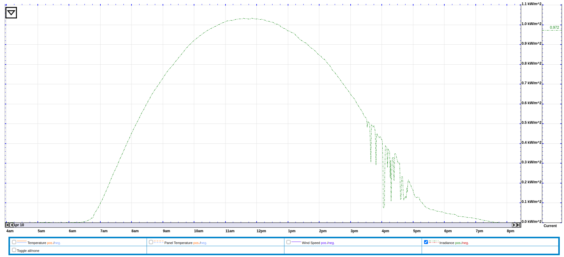](https://kb.egauge.net/uploads/images/gallery/2021-04/image-1619712737118.png) Data from the IMT sensor can also be used in formula registers to calculate the estimated solar production at a site. The formula for this calculation requires real time irradiance and temperature data (obtained from the IMT sensor), the array's rating in watts, and the panel temperature coefficient (usually a small negative number). The following example shows this formula based on a 10kW array and a temperature coefficient of -.12%. [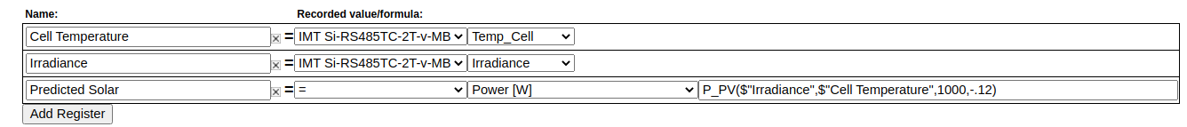](https://kb.egauge.net/uploads/images/gallery/2021-04/image-1619640250900.png) The formula field contains: `P_PV($"Irradiance",$"Cell Temperature",10000,-.12)` --- ### Additional Sensors The IMT sensor supports two additional sensors: a wind speed sensor and an ambient temperature sensor. These sensors connect directly to the IMT sensor body. To connect these sensors, remove the appropriate threaded cap from the sensor body (the wind speed sensor uses the two pin connector, and the ambient temperature sensor uses the three pin connector). In the image below, one cap has been removed (left). [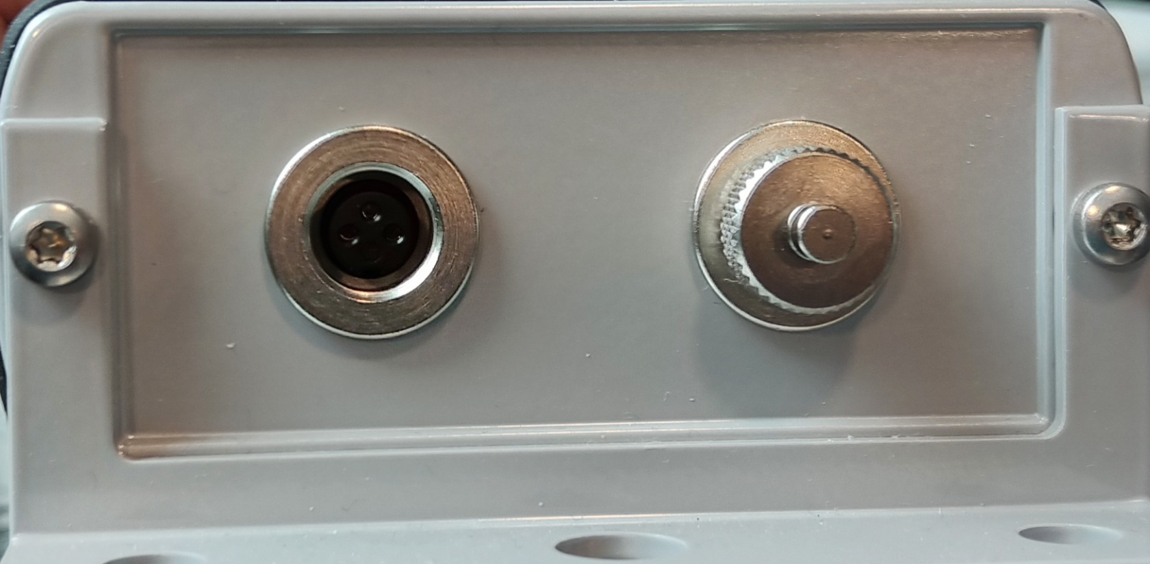](https://kb.egauge.net/uploads/images/gallery/2021-04/image-1619640582003.jpg) When using an add-on sensor, the configuration is exactly the same *except* additional registers will need to be created to record data from the add-on sensors.Do not connect anything besides official IMT add-on sensors to these ports. Doing so will cause damage and void the warranty on the IMT sensor.
--- ### Suggested Reading - [RS485-USB adapter](https://kb.egauge.net/books/egauge-hardware-product-pages/page/egauge-usb-serial-converter-%28usb485%29) - [General information on connecting remote devices via RS485-USB adapter](https://kb.egauge.net/books/egauge-meter-communication/page/remote-device-via-egauge-usb485-adapter) - [RS485-Ethernet adapter (BF430)](https://kb.egauge.net/books/egauge-hardware-product-pages/page/rs485-to-ethernet-converter-%28bf430%29) - [Remote devices and third party devices](https://kb.egauge.net/books/egauge-meter-configuration/page/remote-devices-and-third-party-devices) # Sensor Hub (ESH044) ##### [ Visit the online store page](https://store.egauge.net/sensor-hub "Visit the online store now!") ##### Model: ESH044For use with [**supported eGauge sensors**.](https://kb.egauge.net/books/egauge-hardware-product-pages/chapter/environmental-analog-and-other-sensors)
Only use straight-through RJ-11 cables to connect powered sensors to the Sensor Hub. Telephone systems generally use "reverse" style RJ-11 cables which are incompatible with the Sensor Hub. See **[this article](https://kb.egauge.net/books/egauge-installation/page/rj-11-wiring-between-sensor-hub-and-sensors)** for more information on verifying the correct RJ-11 wiring. Every Sensor Hub compatible sensor sold by eGauge Systems comes with a straight-through RJ-11 cable.
The eGauge Sensor Hub can connect up to four sensors to EG4xxx meter inputs. Any combination of powered and non-powered sensors can be used. Switches select whether the powered or non-powered port is connected to the meter. The RJ-45 breakout cable is used to connect the Sensor Hub to up to four neighboring inputs on the meter. The RJ45 coupler can be used to extend the length of the RJ45 cable as needed. Multiple Sensor Hubs can be used to connect more than four sensors to a meter. For current transformers (CTs), the Sensor Hub provides a convenient method to extend CT cable length without requiring splicing or modifying the CT leads.For current transformers (CTs) total **combined** distance for the RJ45 cable and CT leads must not exceed 100'/33m.
For [powered sensors](https://kb.egauge.net/books/egauge-hardware-product-pages/chapter/environmental-analog-and-other-sensors "Environmental, Analog and Other Sensors"), the Sensor Hub provides a convenient method to adapt from the sensor's RJ11 cable to the 2-pin terminal plug of the EG4xxx meter. The 5V supply required for these sensors can be provided via mini-USB cable or 2-pin terminal plug.For powered sensors total **combined** distance for the RJ45 cable and CT leads must not exceed 1650'/500m.
[See our Sensors product introduction video here](https://www.youtube.com/watch?v=6D82guIQP50&feature=youtu.be).| [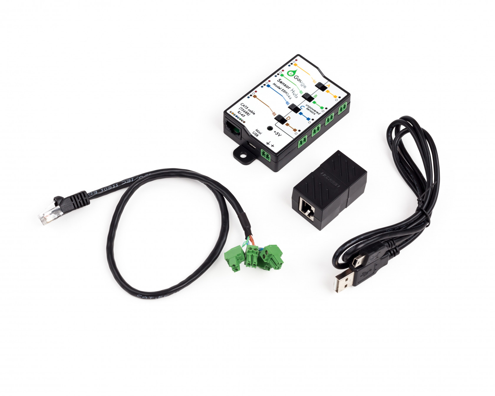](https://kb.egauge.net/uploads/images/gallery/2020-06/sensor-hub-kit.jpg) *eGauge Sensor Hub (ESH044)* |
Only input +5Vdc to the power terminal (if not using USB) when using powered sensors (RJ-11 connections). Other voltages will cause damage.
- The switch must be in the correct position (left for RJ11 connected sensors, right for 2-pin sensors) - Lines adjacent to the to the inputs have colors that match the 2-pin breakout cable color pairs - If extending CTs, do not install the Sensor Hub inside a distribution or breaker panel, only the CTs should be inside. 1. Connect the sensor to one of the 4 ports on the Sensor Hub. If using CTid powered sensors such as the ETN100 (temperature probe), ETLW (ambient temperature), EPS (pulse), ELV2 (2V analog / dry contact), or EV1000 (high voltage sensor) the sensors connect via RJ11 on the left-side of the Sensor Hub. If extending CTs, the 2-pin plug on the CT lead connect to the 2-pin sockets on the right-side of the Sensor Hub. A combination of CTs and powered sensors may be used. Only a single powered or unpowered sensor may be used on each port (yellow/A, green/B, blue/D, and brown/D). 2. Set each switch to the side the sensor is connected. If a powered sensor is connected to the port adjacent to the yellow line, the adjacent switch should be in the left position. 3. If using powered sensors, the Sensor Hub must be powered by 5V DC. This can be either via Mini-USB or the 2-pin plug to the right of the USB port. Using any voltage except 5V DC will cause damage to attached sensors and possibly the eGauge meter. If only using for CT extensions, **do not** power the Sensor Hub. The LED will turn green when there is power applied. 4. If the distance from the Sensor Hub to the eGauge is ~1 foot or less, connect the included RJ45 to 2-pin breakout cable to the RJ45 port to the left of the USB on the Sensor Hub. If there will be distance between the eGauge meter and Sensor Hub 1. Run a standard CAT5 Ethernet cable between the eGauge and Sensor Hub location. 2. Connect one end of the Ethernet cable to the Sensor Hub RJ45 plug. 3. On the other end, attach the RJ45 coupler (included with the Sensor Hub) to the Ethernet line, then connect the Ethernet to 2-pin breakout cable to the other side of the RJ45 coupler. 5. Connect the 2-pin plugs of the breakout cable to the eGauge sensor ports. The color of the twisted pair wires on the breakout cable match with the colored lines on the Sensor Hub to identify which sensors they are for. See images below. 6. If using a CTid sensor that reads external signals, such as the EC420 or EPS, connect the output of the sensor to the CTid sensor connected to the Sensor Hub. Not all sensors utilize all inputs. Refer to the Assembly/installation information information in the sensor's [product page](https://kb.egauge.net/books/egauge-hardware-product-pages) in the support library for specific information. 7. Finally, [configure the sensors](https://kb.egauge.net/books/sensors/page/configuring-ctid-enabled-sensors) that were connected. ### 2-bin breakout cable colors 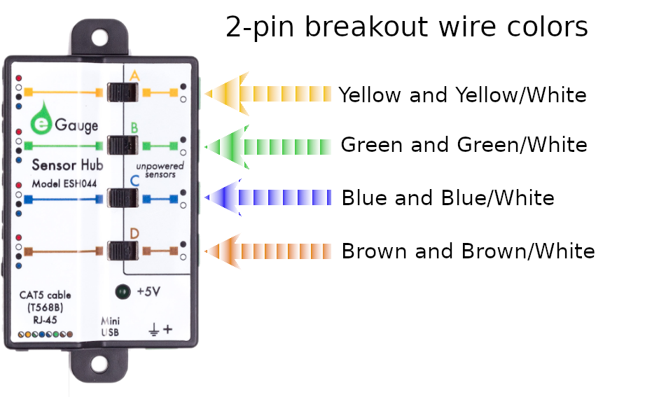| [](https://kb.egauge.net/uploads/images/gallery/2020-02/breakout-cable.png) |
| *RJ-45* to 2-pin breakout cable. Each 2-pin plug uses either green+green/white, blue+blue/white, brown+brown/white, or yellow+yellow/white. |
Requires the [**eGauge Sensor Hub**](https://kb.egauge.net/books/egauge-hardware-product-pages/page/sensor-hub-%28esh044%29 "eGauge Sensor Hub") and eGauge model EG4xxx (Pro or Core), not compatible with older model units.
Only use straight-through RJ-11 cables to connect powered sensors to the Sensor Hub. Telephone systems generally use "reverse" style RJ-11 cables which are incompatible with the Sensor Hub. See **[this article](https://kb.egauge.net/books/egauge-installation/page/rj-11-wiring-between-sensor-hub-and-sensors)** for more information on verifying the correct RJ-11 wiring. Every Sensor Hub compatible sensor sold by eGauge Systems comes with a straight-through RJ-11 cable.
The eGauge High Voltage sensor is used in conjunction with the [Sensor Hub](https://kb.egauge.net/books/sensors/page/sensor-hub-%28esh044%29) and an EG4xxx model meter (Core or Pro) which allows EG4xxx meters to read voltages up to 1,000 VDC or 707 VAC.| [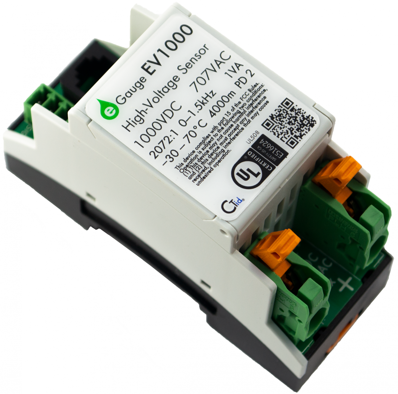](https://kb.egauge.net/uploads/images/gallery/2021-02/main.png) |
| *eGauge EV1000 High Voltage Sensor* |
The high voltage inputs to the EV1000 can be connected Line-to-Line or Line-to-Neutral as long as the voltage potential does not exceed 1,000 VDC or 707 VAC. Safety grounds cannot be used for voltage measurements.
#### Connection to EG4xxx Meter 1. It is not advisable to extend the RJ11 leads from the Sensor to Sensor Hub. It is acceptable to use a longer RJ45 cable from the *Sensor Hub* to the *eGauge*. 2. If RJ11 cable between *Sensor* and *Sensor Hub* must be extended, it is advisable to use twisted pair wires, such as a CAT5 cable with RJ11 plugs (most commonly used for DSL modems). 3. If terminating own cables, both RJ11 and RJ45 cables should be straight-through cables, with the same color order on both ends. 4. See Installation Examples for common use cases of the EV1000. 1. [Install the sensors and Sensor Hub](https://kb.egauge.net/link/174#bkmrk-assembly%2Finstallatio). 2. Connect the EV1000 to a voltage reference no greater than 1000Vdc or 707Vac. 3. [Configure the sensors](https://kb.egauge.net/books/sensors/page/configuring-ctid-enabled-sensors). #### Connection to non-eGauge meter inputs Use the 4-pin connector next to the RJ11 port. +5 VDC and ground is required to power the sensor. SIG+ and SIG- output a ±5V signal proportional to the line inputs. ## Documents - [Manual](https://www.egauge.net/media/support/docs/ev1000-manual.pdf) - [Spec Sheet](https://www.egauge.net/media/support/docs/WEB-EV1000-datasheet.pdf) - [FCC Declaration](https://www.egauge.net/media/support/docs/ev1000-fcc-declaration-of-conformity.pdf) ## Installation Examples - [480V or 600V Delta Service](https://kb.egauge.net/books/egauge-installation/page/monitoring-480v-and-600v-delta-systems) - [347/600V Service](https://kb.egauge.net/books/egauge-installation/page/monitoring-347600v-services) - [Multiple Services](https://kb.egauge.net/books/egauge-installation/page/monitoring-multiple-services-with-one-egauge-meter) ## Related Information - [Sensor Hub Product Page](https://kb.egauge.net/books/egauge-hardware-product-pages/page/sensor-hub-%28esh044%29) - [Configuring CTid Sensors](https://kb.egauge.net/books/egauge-meter-configuration/page/configuring-ctid-enabled-sensors) - [Monitoring 347/600V Wye Services](https://kb.egauge.net/books/advanced-egauge-operation/page/monitoring-347600v-services) ### # 4-20mA Sensor (EC420) ##### [ Visit the online store page](https://store.egauge.net/EC420-current-sensor "Visit the online store now!") ##### Model: EC420Requires the [**eGauge Sensor Hub**](https://kb.egauge.net/books/egauge-hardware-product-pages/page/sensor-hub-%28esh044%29 "eGauge Sensor Hub") and eGauge model EG4xxx (Pro or Core), not compatible with older model units.
Only use straight-through RJ-11 cables to connect powered sensors to the Sensor Hub. Telephone systems generally use "reverse" style RJ-11 cables which are incompatible with the Sensor Hub. See **[this article](https://kb.egauge.net/books/egauge-installation/page/rj-11-wiring-between-sensor-hub-and-sensors)** for more information on verifying the correct RJ-11 wiring. Every Sensor Hub compatible sensor sold by eGauge Systems comes with a straight-through RJ-11 cable.
The eGauge 4-20mA Sensor is used in conjunction with the [Sensor Hub](https://kb.egauge.net/books/sensors/page/sensor-hub-%28esh044%29) and an EG4xxx model meter (Core or Pro) to read a 4-20mA current loop sensor such as pressure sensors, water level sensors, temperature probes, and other industrial sensors that output a 4-20mA current loop. [See our Sensors product introduction video here](https://www.youtube.com/watch?v=6D82guIQP50&feature=youtu.be).| [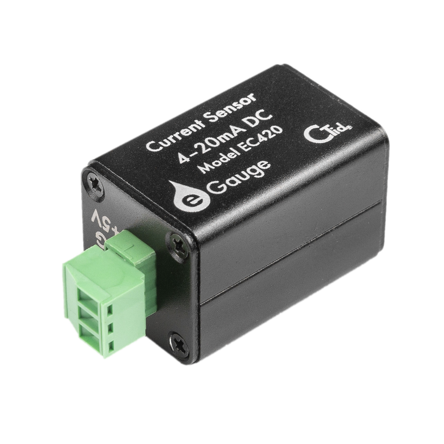](https://kb.egauge.net/uploads/images/gallery/2021-08/image-1628193345184.jpg) |
| *eGauge EC420 4-20mA Sensor* |