Current Transformers (CTs)
- AC Split-Core CTs with CTid
- AC Split-Core CTs (J&D)
- High-Accuracy AC Split-Core CTs (AccuCT)
- AC Rope CTs (Rogowski Coil)
- CTid-enabled AC Rope CT (ERA-XXX-YYYY)
- Large 50mm (2.00") AC Split-Core CTs
- Large High-Accuracy 80mm (3.1") CTs (AccuEnergy)
- DC Split-Core CTs (eGauge DC CTs)
- DC (Direct Current) CTs
AC Split-Core CTs with CTid
Visit the online store page (1% Accuracy)
Visit the online store page (0.5% Accuracy)
- These are the new CTid-enabled CTs produced by eGauge Systems. An EG4xxx series meter is required for CTid functionality.
- The CTs rated current should be the smallest available rating that is at least as high as the maximum current of the rated circuit.
- The CTs may not be installed in equipment where they exceed 75% of the wiring space of any cross-sectional area within the equipment.
- Do not install CTs where they may block ventilation openings.
- Do not install CTs in the area of breaker arc venting.
- Not suitable for Class 2 wiring methods.
- Not intended for connection to Class 2 equipment.
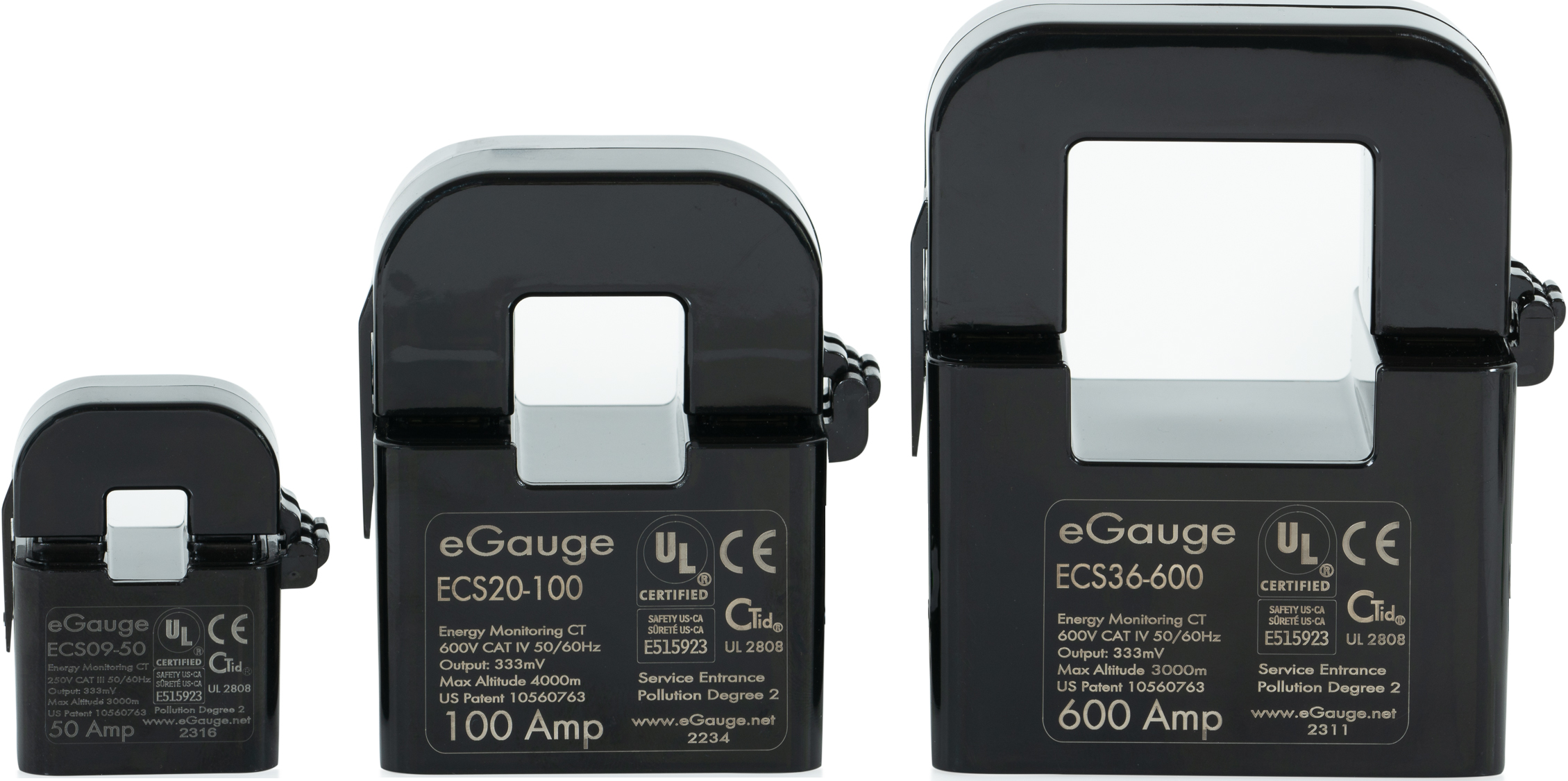
The ECS20 and ECS36 CTs may be used to measure bare (non insulated) conductors and on service entrance conductors up to 600V. ECS09 are rated for insulated conductors on CAT III up to 250V
AC split-core CTs measures the amperage of a conductor on an AC (alternating current) system. Combined with voltage measurements, this allows calculation of power and energy values. AC CTs provided by eGauge are split-core, meaning they can be wrapped around a conductor instead of having to disconnect the conductor and feed it through the CT.
The eGauge ECS CT series have CTid technology and contain a locator LED that can be blinked to identify which CT is connected to a given sensor port. This is useful if the CT leads cannot be traced.
eGauge ECS CTs are also UL2808 certified and may be used on bare metal or insulated wires up to 600V in Category IV environments.
ECS CTs are available with 1% accuracy (ECSxx-yyy) and 0.5% accuracy (ECSxx-yyy-R).
|
|
|
eGauge ECS Split-Core AC CTs. The CTid LED can be seen through the transparent window on the bottom of the CT. |

Specifications
Full specs (data-sheet PDF)
- Accuracy: 1% and 0.5% models available
- Amperage ratings:
- ECS09 (9mm): 50A, 80A
- ECS20 (20mm): 100A, 200A, and 300A
- ECS36 (36mm): 400A and 600A
- ECS09 (9mm): 50A, 80A
- Frequency: 50–60Hz
- Temperature range
- ECS09 and ECS20: -40 °C to 75 °C (-40 °F to 167 °F), 95% RH non-condensing
- ECS36: -40 °C to 60 °C (-40 °F to 140 °F), 95% RH non-condensing
- Working voltage
- ECS09: 250VAC, CAT III
- ECS20 and ECS36: 600VAC, CAT IV
- ECS09: 250VAC, CAT III
- Indoor use, Pollution Degree 2, Altitude up to 3000m
- Output: 333mVrms at rated amperage
- 18 or 22 AWG twisted-pair leads (UL1015 600V)
- UL2808, UL61010-1, RoHS
- CE Pending
- 5-year Limited Warranty
Hardware included
- 1x ECS AC CT with built-in 8 foot leads and 2-pin plug affixed
Assembly/installation information
The ECS series CTs are a CTid enabled sensor. They are physically installed in the same manner as conventional CTs, but are configured using CTid. See this article for more information on configuring CTid enabled sensors.
Point the arrow on the CT in the same direction of the normal current flow.
See the Installation Overview Tips to get started.
-
To reduce risk of electric shock, open or disconnect circuits from the power distribution system (or service) of the building before installing or serving CTs.
- Open the CT by gently pulling on the latch and then rotating the top open. Do not touch the polished ferrite core surfaces. Any oils or debris in that area worsens accuracy.
- Slide the CT over the conductor of the circuit to be measured. Make sure the arrow on the CT points in the direction of the normal current flow (the current flow that should yield a positive power reading).
- Close the CT by gently pushing down on top of the CT until the latch engages.
- Verify that the CT is fully closed by squeezing together the top and bottom parts of the CT.
- Optional: secure the CT to the conductor with a cable tie.
- Route the twisted pair wires of the CT to the meter such that they do not directly contact live terminals or bus bars.
- Plug the 2-pin terminal at the end of the twisted pair wires into an unused port on the meter.
- When connected to an EG4xxx meter, use the CTid® scanning feature to automatically detect the sensor type and its current rating. If using an older model meter, use the drop-down method to Configure the sensor input.
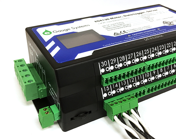 |
| CTs connected to eGauge meter. |
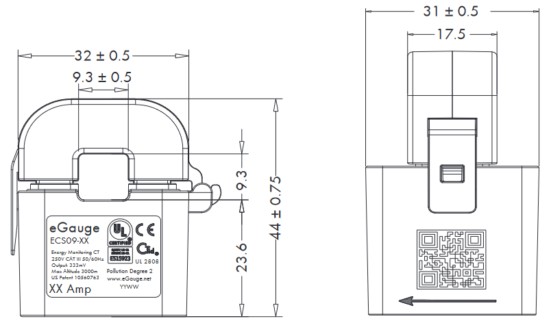
Dimensional Diagrams
ECS09
ECS20 (click to enlarge)

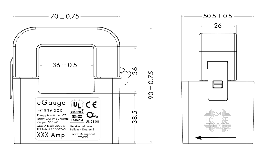
ECS36 (click to enlarge)
Documents
- eGauge ECS datasheet
- ECS series CT installation guide insert
- ANSI revenue grade accuracy certification
Related Information
- CT Selection Guide
- Configuring CTid-enabled sensors
- EG4xxx Certification Documents and Declarations
- 2-Pin Plug
AC Split-Core CTs (J&D)
Visit the online store page
AC split-core CTs measures the amperage of a conductor on an AC (alternating current) system. Combined with voltage measurements, this allows calculation of power and energy values. AC CTs provided by eGauge are split-core, meaning they can be wrapped around a conductor instead of having to disconnect the conductor and feed it through the CT. For pricing and available models, see the online store.
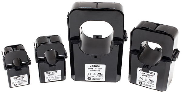
This article covers CT diameters from 10mm (.39") to 36mm (1.42"). For larger sized CTs, see the Rope CT article or Large 50mm (2.00") CT article. It is recommended to use Rope CTs over the 50mm split-core CTs.
For C0.6 certified high-accuracy split-core CTs, see the High-Accuracy CT product page.
|
|
| Standard split-core CTs in multiple sizes |
Specifications
Full specs (data-sheet PDF)
- 333 mVrms at rated output
- Accurate within 1% from 1% to 100% of rated amperage
- Operates 50Hz/60Hz
- Maximum primary insulation up to 600 Vrms
- 8' twisted pair lead with CT connector
- 1-year Limited Warranty
Hardware included
- 1x J&D split-core CT with built-in 8 foot leads and 2-pin plug affixed
Assembly/installation information
See the Installation Overview Tips to get started.
-
To reduce risk of electric shock, open or disconnect circuits from the power distribution system (or service) of the building before installing or serving CTs.
- Open the CT by gently pulling on the latch and then rotating the top open. Do not touch the polished ferrite core surfaces. Any oils or debris in that area worsens accuracy.
- Slide the CT over the conductor of the circuit to be measured. Make sure the sticker on the CT points in the direction of the primary current flow (the current flow that should yield a positive power reading).
- Close the CT by gently pushing down on top of the CT until the latch engages. Some CTs require 2 clicks to fully shut.
- Verify that the CT is fully closed by squeezing together the top and bottom parts of the CT.
- Optional: secure the CT to the conductor with a cable tie.
- Route the twisted pair wires of the CT to the meter such that they do not directly contact live terminals or bus bars.
- Plug the 2-pin terminal at the end of the twisted pair wires into an unused port on the meter.
- Configure the sensor input in the meter interface and complete the general configuration.
|
| CTs connected to eGauge meter. |
Documents
Related Information
High-Accuracy AC Split-Core CTs (AccuCT)
Visit the online store page
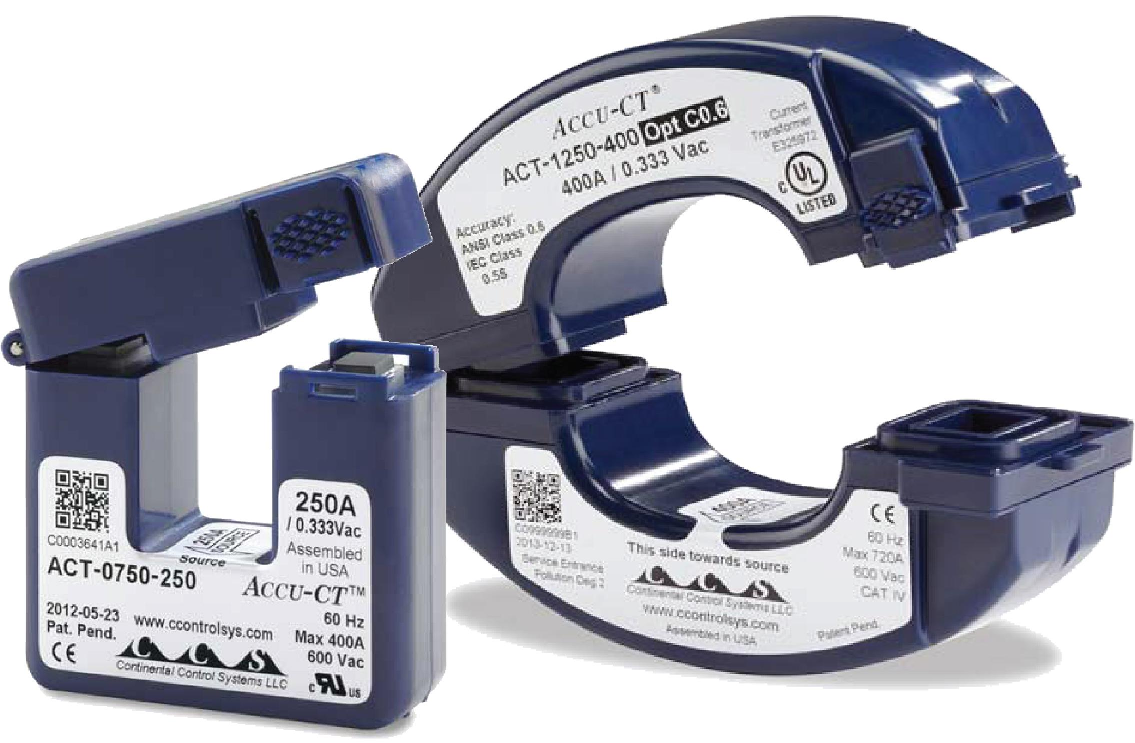
High-Accuracy AC Split-Core CTs work the same as standard AC Split-Core CTs but are certified for ANSI C12.20 0.5% accuracy when used with eGauge meters. Some applications such as revenue billing may require certified CTs to be used. For pricing and available models, see the online store.
Larger, 80mm 0.5% ANSI revenue grade accurate CTs are also available.
|
|
| C0.6 certified high-accuracy CTs |
Specifications
Full specs (data-sheet PDF)
- ANSI C12.20 0.5% revenue grade accurate with eGauge Core or Pro meter
- UL 2808 Listed, CE mark, RoHS
- IEEE/ANSI C57.13, Class 0.6
- IEC 60044-1 0.5s class
- 333.33 mVrms voltage output at rated full scale current
- Optional C0.6 certificate when ordered
- 2.4m (8') twisted pair 20 AWG lead with CT connector
- 50/60 Hz
- 5-year Limited Warranty
- 20mm version:
- -40 °C to 80 °C
- CAT III: 600 Vac
- CAT IV (service entrance): 250 Vac
- 32mm version:
- -30 °C to 75 °C
- CAT III: 250 Vac
- CAT IV (service entrance): 600 Vac
Hardware included
- 1x AccuCT split-core CT with built-in 8 foot leads and 2-pin plug affixed
Assembly/installation information
See the Installation Overview Tips to get started.
-
To reduce risk of electric shock, open or disconnect circuits from the power distribution system (or service) of the building before installing or serving CTs.
- Open the CT by gently squeezing the textured latch and then rotating the top open. Do not touch the polished ferrite core surfaces. Any oils or debris in that area worsens accuracy.
- Slide the CT over the conductor of the circuit to be measured. Make sure the sticker on the CT points in the direction of the primary current flow (the current flow that should yield a positive power reading).
- Close the CT by gently pushing down on top of the CT until the latch engages.
- Verify that the CT is fully closed by squeezing together the top and bottom parts of the CT.
- Optional: secure the CT to the conductor with a cable tie.
- Route the twisted pair wires of the CT to the meter such that they do not directly contact live terminals or bus bars.
- Plug the 2-pin terminal at the end of the twisted pair wires into an unused port on the meter.
- Configure the sensor input in the meter interface and complete the general configuration.
|
| CTs connected to eGauge meter. |
Documents
Related Information
AC Rope CTs (Rogowski Coil)
Visit the online store page
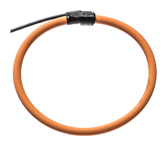
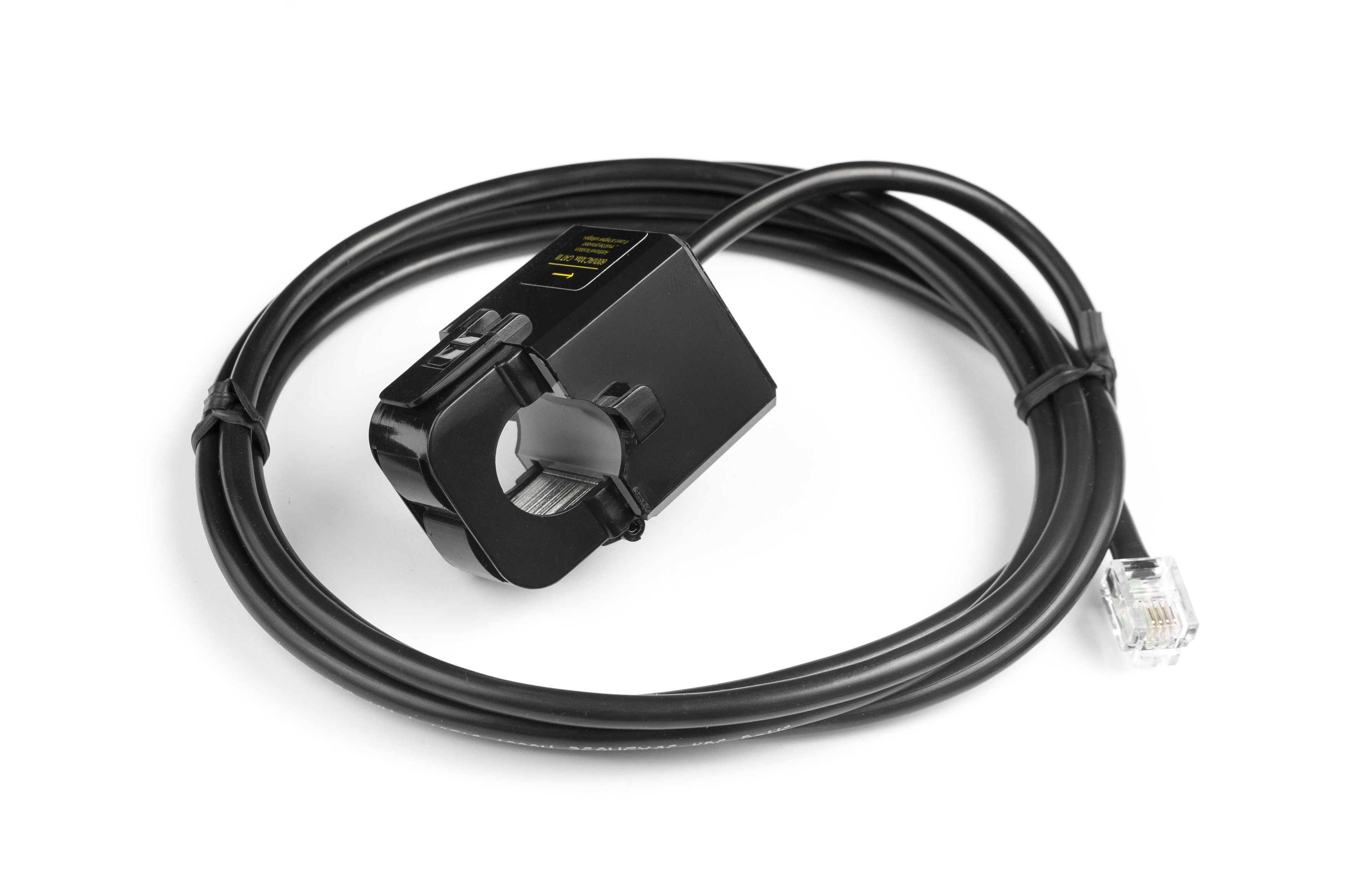
Rope CTs (technically called Rogowski Coils) are large, flexible sensors for monitoring current like split-core CTs. Rope CTs are installed similar to standard split-core CTs, where a connector on the rope allows it to be opened and placed around a conductor without needing to thread the conductor through it. For pricing and available models, visit the online store.
Rope CTs are designed for 20-30 amps or greater load. Lower amperage results in lower accuracy readings.
Face the arrow on the rope towards what you want to measure. Positive power polarity when power is against the arrow, and negative when it is the same direction the arrow points.
The position of the Rope CT on the conductor affects accuracy. See this article for more information.
Why use a Rope CT?
Rope CTs are excellent for bus-bars and large switch-gear applications that standard split-core CTs cannot fit around. Rope CTs are flexible and easy to install but require a minimum amperage of approximately 30A for accuracy.
|
|
| Rope CT |
Specifications
Full specs (data-sheet PDF)
- Operates 50Hz/60Hz
- Accurate within 1% from 30A to stated current rating
- Maximum primary insulation up to 600 Vrms
- 2m (6.5') wire lead with CT connector
- Notes: 30A minimum current required at all times.
- No external integrator required
- 5-year Limited Warranty
Hardware included
- 1x Rope CT with built-in 8 foot leads and 2-pin plug affixed
Assembly/installation information
See the Installation Overview Tips to get started.
-
To reduce risk of electric shock, open or disconnect circuits from the power distribution system (or service) of the building before installing or serving CTs.
- Open the rope CT by gently pulling squeezing the latch and pulling the end of the rope CT out. Do not touch the inside surfaces where the CT opens. Any oils or debris in that area worsens accuracy.
- Wrap the rope CT over the conductor of the circuit to be measured. Make sure the arrow on the rope CT points in the direction of the primary current flow (the current flow that should yield a positive power reading).
- Close the rope CT by gently squeezing the latch and inserting the other end inside the latching end and release the latch.
- Verify that the rope CT is fully closed.
- Optional: secure the CT to the conductor with a cable tie.
- Route the twisted pair wires of the CT to the meter such that they do not directly contact live terminals or bus bars.
- Plug the 2-pin terminal at the end of the twisted pair wires into an unused port on the meter.
- Configure the sensor input in the meter interface and complete the general configuration.
|
| CTs connected to eGauge meter. |
Documents
Related Information
- Rope CT positioning and accuracy guide
- What CT do I choose from the configuration menu?
- CT Selection Guide
CTid-enabled AC Rope CT (ERA-XXX-YYYY)
Visit the online store page
This article is for the ERA-XXX-YYYY CTid enabled Rope CT. For the non-CTid enabled ropes (RCT-XXX-YYYY) please visit this article. In the upcoming future all Rope CTs will be CTid-enabled. Check the model number on the tag of the Rope CT to verify which version you have. CTid enabled Ropes start with ERA, and ones without CTid start with RCT.
Information on configuring CTid sensors can be found here.
Rope CTs (technically called Rogowski Coils) are large, flexible sensors for monitoring current like split-core CTs. Rope CTs are installed similar to standard split-core CTs, where a connector on the rope allows it to be opened and placed around a conductor without needing to thread the conductor through it. For pricing and available models, visit the online store.
The ERA Rope CT contains CTid. It is the same as the RCT-XXX-YYYY model but has a different style connector and contains CTid for auto-detection and has an onboard LED that can be used to identify which CT is connected to a given sensor port, which can be useful if the CT leads cannot be traced from the meter to the conductors being monitored.
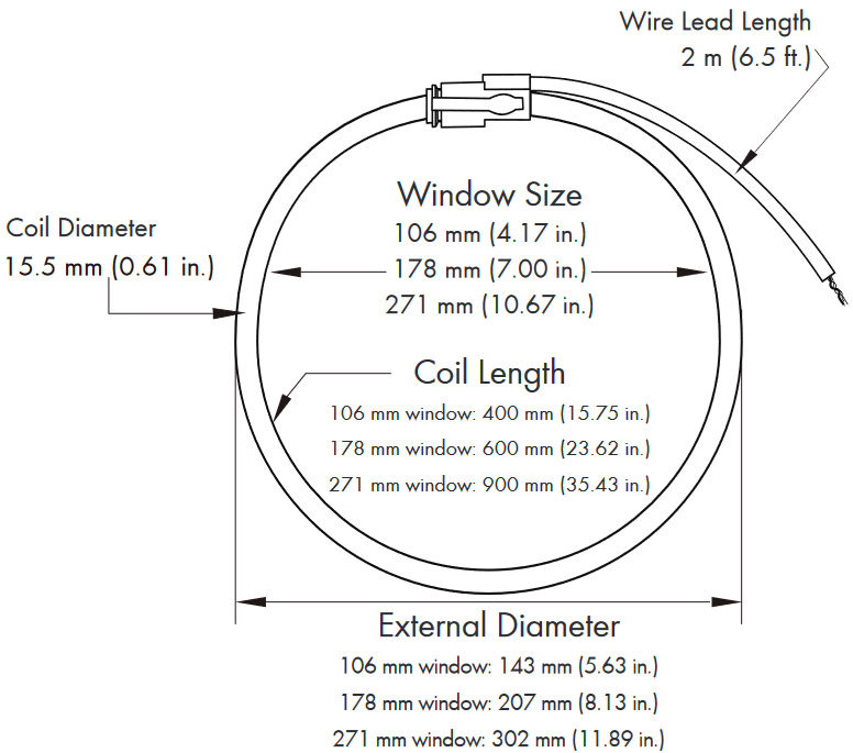
The CTid-enabled Ropes are available in sizes of 106 mm (2775 A max), 178 mm (2775 A or 6935 A max), and 271 mm (6935 A max). Please see the online store or data sheet for available combinations.
Rope CTs are designed for 20-30 amps or greater load. Lower amperage results in lower accuracy readings.
Face the arrow on the rope towards what you want to measure. Positive power polarity when power is against the arrow, and negative when it is the same direction the arrow points.
The position of the Rope CT on the conductor affects accuracy. See this article for more information.
Why use a Rope CT?
Rope CTs are excellent for bus-bars and large switch-gear applications that standard split-core CTs cannot fit around. Rope CTs are flexible and easy to install but require a minimum amperage of approximately 30A for accuracy.
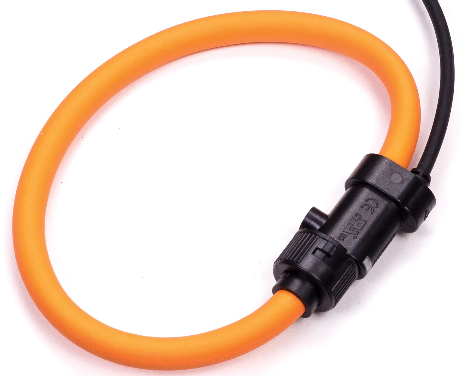 |
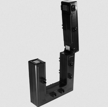
| ERA-106-2775 Rope CT |
Specifications
Full specs (data-sheet PDF)
- CTid Enabled
- Max Amperage: 2775 A or 6935 A
- Window sizes: 106 mm (4.17in.), 178mm (7.00 in.), or 271 mm (10.67 in.)
- Frequency Range: 50 Hz or 60 Hz
- Operating Temperature: -20 °C to 70 °C
- Overvoltage Category: 1000V CAT III, 600V CAT IV
- Positional: Error Better than 4%
- Linearity: Better than 1%
- Material: Orange thermoplastic rubber; flame retardant UL 94 V-0 rated
- Cable: 1000V UL style 20940; External diameter 5mm; Wires 2x 26AWG
- 5-year Limited Warranty
Dimensions (click to enlarge)
Hardware included
- 1x Rope CT with built-in 8 foot leads and 2-pin plug affixed
Assembly/installation information
The ERA-XXX-YYYY is a CTid enabled sensor and is configured differently than conventional CTs. See this article for more information on configuring CTid enabled sensors.
See the Installation Overview Tips to get started.
-
To reduce risk of electric shock, open or disconnect circuits from the power distribution system (or service) of the building before installing or serving CTs.
- Open the rope CT by gripping and twisting the bayonet connector and pulling the end of the rope CT out. Do not touch the inside surfaces where the CT opens. Any oils or debris in that area worsens accuracy.
- Wrap the rope CT over the conductor of the circuit to be measured. Make sure the arrow on the rope CT points in the direction of the primary current flow (the current flow that should yield a positive power reading).
- Close the rope CT by gently squeezing the latch and inserting the other end inside the latching end and release the latch.
- Verify that the rope CT is fully closed.
- Optional: secure the CT to the conductor with a cable tie.
- Route the twisted pair wires of the CT to the meter such that they do not directly contact live terminals or bus bars.
- Plug the 2-pin terminal at the end of the twisted pair wires into an unused port on the meter.
- When connected to an EG4xxx meter, use the CTid® scanning feature to automatically detect the sensor type and its current rating. If using an older model meter, use the drop-down method to Configure the sensor input.
|
| CTs connected to eGauge meter. |
Documents
Related Information
- Rope CT positioning and accuracy guide
- Configuring CTid enabled sensors
- What CT do I choose from the configuration menu?
- CT Selection Guide
Large 50mm (2.00") AC Split-Core CTs
Visit the online store page
Large AC Split-Core CTs are in principal the same as the standard sized AC Split-Core CTs but are physically much larger and have a lower accuracy. In most cases, it is better to use a Rope CT instead. For pricing and available models, see the online store.
- 2" CTs are relatively large at 4.75" x 5" x 1.2", ensure there is enough room in the panel
- Low end accuracy is poorer than other CT options
- Special restock fees may apply if returned
- Lead time may be longer than other CT options
|
|
| Large 2" split-Core CT |

Specifications
Full specs (data-sheet PDF)
- 333 mVrms at rated output
- Accurate within 1% from 10% to 100% of rated amperage
- Operates from 50Hz to 400Hz
- Maximum primary insulation up to 600Vrms
- 8' twisted pair lead with CT connector
- 2" CTs are 4.75" x 5" x 1.2"
- 1-year Limited Warranty
Hardware included
- 1x large split-core CT with built-in 8 foot leads and 2-pin plug affixed
Assembly/installation information
See the Installation Overview Tips to get started.
-
To reduce risk of electric shock, open or disconnect circuits from the power distribution system (or service) of the building before installing or serving CTs.
- Open the CT by holding the bottom part of the CT still and pulling the top part off. Do not touch the polished ferrite core surfaces. Any oils or debris in that area worsens accuracy.
- Slide the CT over the conductor of the circuit to be measured. Make sure the sticker on the CT points in the direction of the primary current flow (the current flow that should yield a positive power reading).
- Close the CT by gently pushing the top part of the CT back onto the bottom part and it clicks shut.
- Verify that the CT is fully closed by squeezing together the top and bottom parts of the CT.
- Optional: secure the CT to the conductor with a cable tie.
- Route the twisted pair wires of the CT to the meter such that they do not directly contact live terminals or bus bars.
- Plug the 2-pin terminal at the end of the twisted pair wires into an unused port on the meter.
- Configure the sensor input in the meter interface and complete the general configuration.
|
| CTs connected to eGauge meter. |
Documents
Related Information
Large High-Accuracy 80mm (3.1") CTs (AccuEnergy)
Visit the online store page
eGauge Systems offers the 80mm AccuEnergy AcuCT-3135R revenue-grade CT in 1,000 A and 1,500 A ratings. For smaller sizes and amperage ratings, see our 20mm and 36mm High-Accuracy CT offerings which offer ANSI C12.20 0.5% accuracy when used with eGauge meters.
|
|
| AcuCT-3135R |
Specifications
Full specs (data-sheet PDF)
- ANSI C12.20 0.5% revenue grade accurate when used with the eGauge Core or Pro meter
- Window size: 80mm (3.15'')
- UL 2808 Listed, 61010-1, and CSA 22.2
- IEC 60044-1 0.5s class
- 333.33 mVrms voltage output at rated full scale current
- 2.4m (8') twisted pair 22 AWG lead with CT connector
- -15 to 65 °C
- 50/60 Hz
- CAT III: 600 Vac
- Pollution Degree 2
- 5-year Limited Warranty
Hardware included
- 1x AcuCT-3135R split-core CT with built-in 8 foot leads and 2-pin plug affixed
- Mounting accessories
- 4x metal surface-mounting tabs
- 5x conductor-mounting set (screw, nut, and plastic standoff)
Assembly/installation information
See the Installation Overview Tips to get started.
-
To reduce risk of electric shock, open or disconnect circuits from the power distribution system (or service) of the building before installing or serving CTs. Ensure any mounting is performed in compliance with all local and national electrical codes.
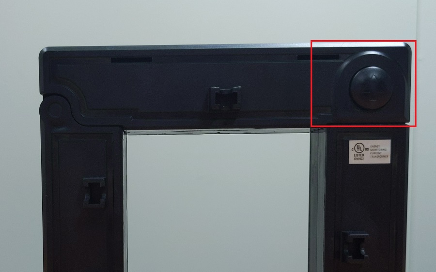
- Open the CT by gently squeezing the latch buttons (circular buttons with an up arrow on the side opposite the hinge, see below for an image). Do not touch the polished ferrite core surfaces. Any oils or debris in that area worsens accuracy.
- Slide the CT over the conductor of the circuit to be measured. Make sure the arrow on the bottom of the CT points in the same direction of the primary current flow (the current flow that should yield a positive power reading).
- Close the CT by gently pushing down on top of the CT until the latch engages. The CT may click twice.
- Verify that the CT is fully closed by squeezing together the top and bottom parts of the CT.
- Optional: secure the CT using the mounting options.
- Route the twisted pair wires of the CT to the meter such that they do not directly contact live terminals or bus bars.
- Plug the 2-pin terminal at the end of the twisted pair wires into an unused port on the meter.
- Configure the sensor input in the meter interface and complete the general configuration.
|
|
| AcuCT-3135R latch button to open CT window, one on each side |
|
| CTs connected to eGauge meter. |
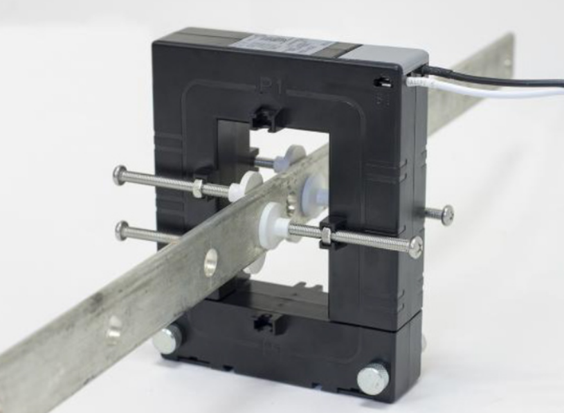
Mounting Options
Do not attempt to use mounting accessories to have the CTs weight held by the conductor being measured. The CT should be resting or mounted directly to a surface.
AcuCT-3135R come with mounting parts that may be used to secure the CT. The original manufacturer's mounting information may be found here.
Busbar or Cable:
- Place the screw caps at the end of the screws
- Position the washer on the screw to the desired position on the screw
- Insert washer into the small opening located near the window of the CT so that the screw cap is touching busbar/cable
- Ensure that the screw caps are firmly securing the busbar and cable
For mounting the CT on a surface, the following should be applied:
- Place the mounting clips in the slots located by the removable top portion
- Ensure mounting clips are securely placed in the slots
- Using four screws (not included), place the screws through the mounting clips and tighten to attach to surface
AcuCT-3135R Mounting Options |
Documents
Related Information
- CT Selection Guide
- What CT do I choose from the configuration menu?
- Other supported Current Transformers
DC Split-Core CTs (eGauge DC CTs)
Visit the online store page
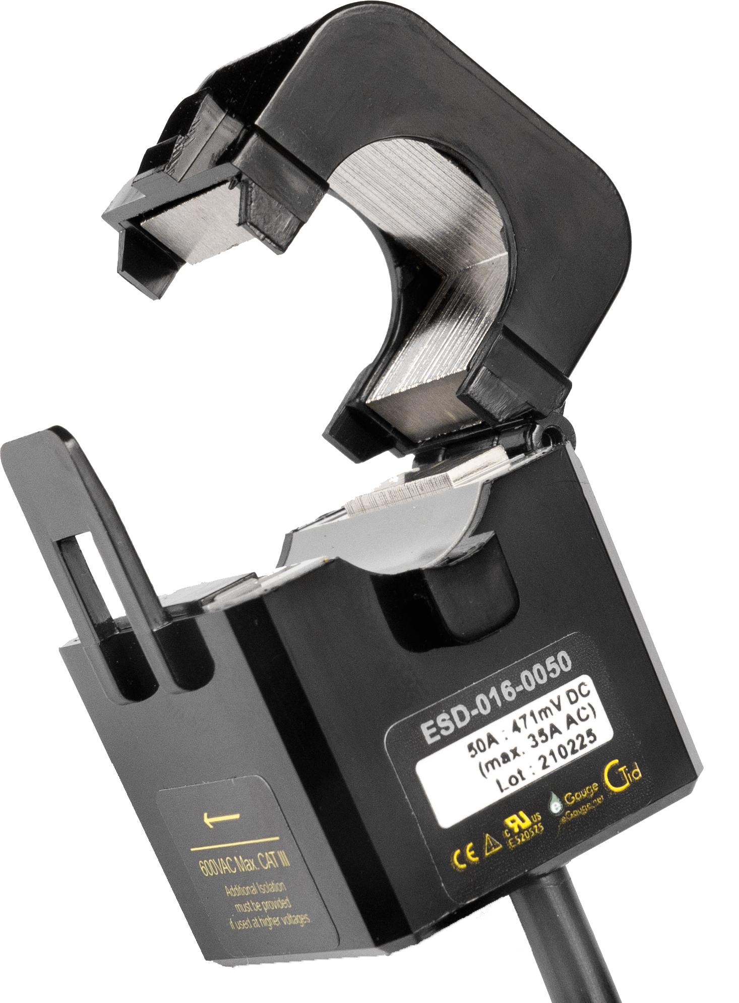
eGauge DC CTs (model ESD-xxx-yyyy) measure the amperage on the conductor of a DC (direct current) system. Combined with DC voltage measurements (through the DC port on the eGauge meter, or the high voltage EV1000 sensor) this allows DC power and DC energy calculations. DC CTs do not need to be used in conjunction with DC voltage measurements to simply measure amperage.
eGauge Systems currently offers 16mm 50A, 24mm 100A, and 36mm 300A DC CTs.
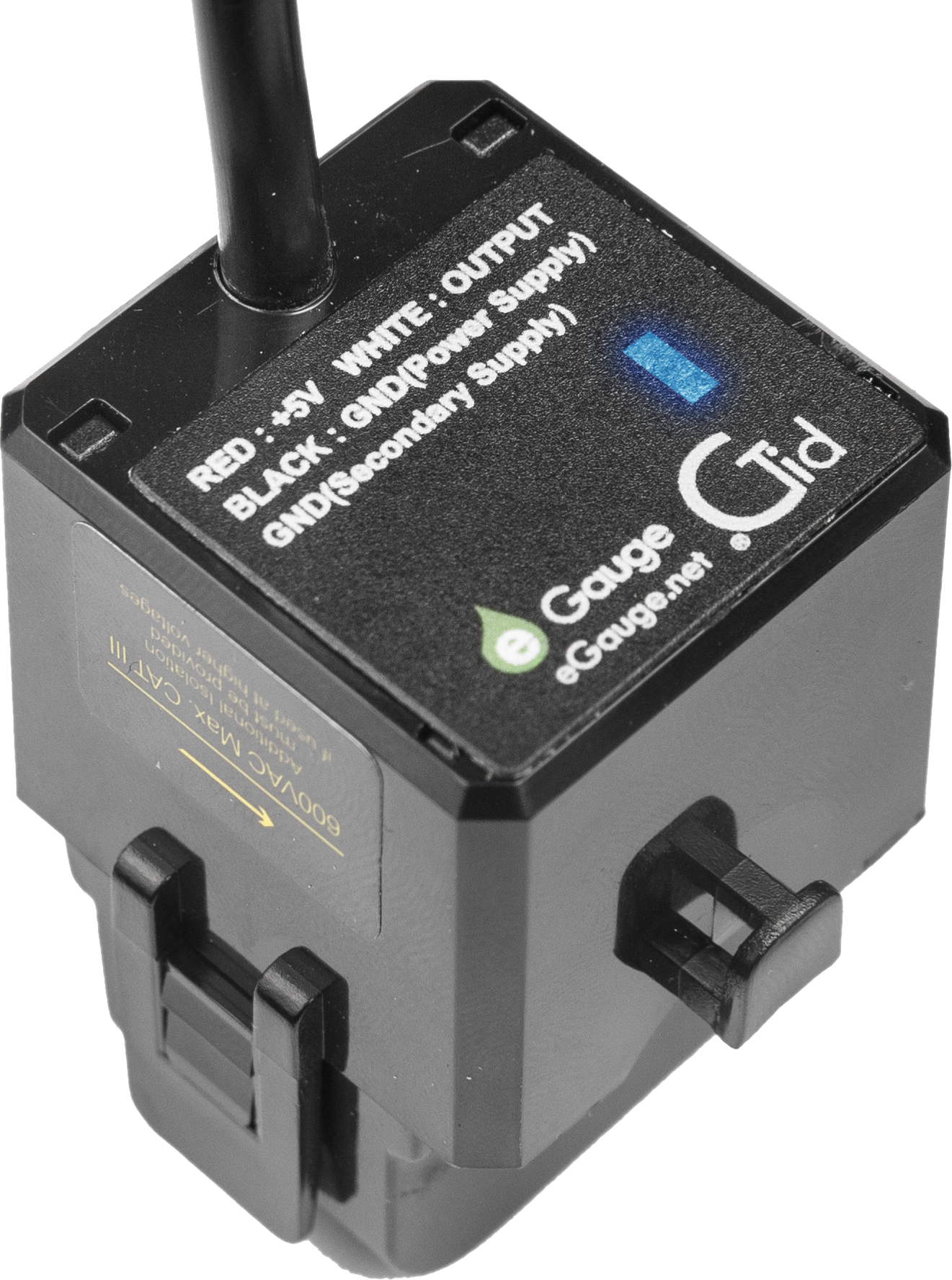
The eGauge DC CTs contain CTid for auto-detection and has an onboard LED that can be used to identify which CT is connected to a given sensor port, which can be useful if the CT leads cannot be traced from the meter to the conductors being monitored.
eGauge DC CTs require a Sensor Hub and are compatible with EG4xxx (Core and Pro) series. Legacy model meters (eGauge2, EG30xx) are not compatible.
|
||
| eGauge Split-Core DC CT model ESD-016-0050. The CTid LED can be seen on the bottom of the CT illuminated in blue. |
Specifications
Full specs (data-sheet PDF)
- Linearity: Better than 2%
- Offset Error: Better than 1.5% of range
- Operating Temperature: -25 °C to 75 °C, 85% RH non-condensing
- 5' lead (RJ-11 terminated to connect to Sensor Hub)
Hardware included
- 1x ESD DC CT w/ attached 5' lead
Assembly/installation information
When current flows with the direction of the arrow, a positive amperage will be read. When current flows against the arrow, the amperage will read negative.
Be sure to see the Installation Overview Tips to get started.
- To reduce risk of electric shock, open or disconnect circuits from the power distribution system (or service) of the building before installing or serving CTs.
- Open the CT by gently pulling on the latch and then rotating the top open. Do not touch the polished ferrite core surfaces. Any oils or debris in that area worsens accuracy.
- Slide the CT over the conductor of the circuit to be measured. Make sure the arrow on the CT points in the direction of the primary current flow (the current flow that should yield a positive power reading).
- Close the CT by gently pushing down on top of the CT until the latch engages.
- Verify that the CT is fully closed by squeezing together the top and bottom parts of the CT.
- Optional: secure the CT to the conductor with a cable tie.
- Route the RJ-11 cable of the CT to the Sensor Hub such that they do not directly contact live terminals or bus bars.
- Follow these instructions for Sensor Hub connection. Note: The DC CT is a powered sensor and the Sensor Hub requires +5V or a USB for power (the USB port on the eGauge meter may be used for this).
- Use the CTid® scanning feature to automatically detect the sensor type and its current rating.
Documents
Related Information
DC (Direct Current) CTs
Visit the online store page
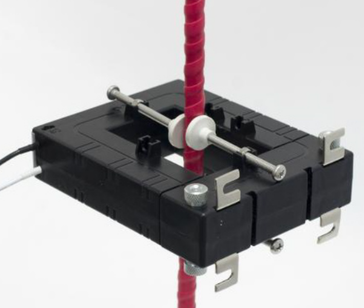
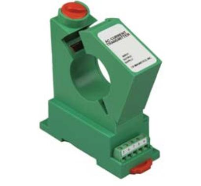
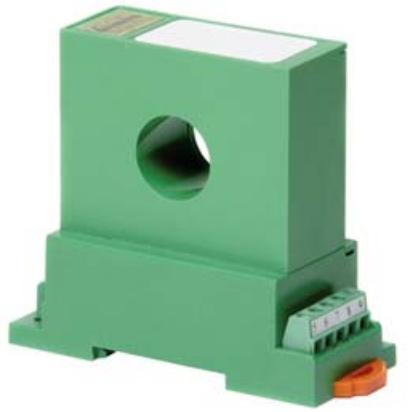
DC CTs measure Direct Current, as opposed to Alternating Current like standard split-core CTs monitor. Direct Current CTs are available in both split-core and solid-core versions. The DC CTs currently offered are Hall Effect style, uni-directional and require a 12Vdc power supply and special leads provided by eGauge. For pricing and available models, see the online store.
Please see the wiring information sheet before installing. Use of special leads (provided) are required for use with the eGauge. Damage may occur if installed without leads or improperly.
|
|
|
| Split-core DC CT | Solid-core DC CT |
Specifications
Full specs (data-sheet PDF)
- Basic Accuracy: 1.0 %
- Linearity: 10% to 100% FS
- Thermal Drift: 500 PPM/°C
- Operating Temperature: 0°C to +50°C
- Installation Category: CAT II
- Isolation Voltage: 3500KVRMS/1mA/1Sec
- Response Time: 250 ms
- Insulation Voltage: 2500 VDC
- Supply Voltage: 12 VDC ±10%
- Weight: 0.5 lbs.
Hardware included
- 1x 12V DC CT
- 1x 8' twisted pair leads w/ resistor and 2-pin plug affixed
- 1x 12Vdc power supply
Assembly/installation information
See the Installation Overview Tips to get started.
The DC CT outputs 4-20mA and requires special leads to convert the signal. Damage may occur if installed without leads or improperly.
- The manufacturer offers both 12Vdc and 24Vdc versions; eGauge supplies the 12Vdc version.
- The direction of current matters; the DC CT will read up to 100% of the current rating if current flows in the "X" and out the "O" side; reversing this will cause the DC CT to read at maximum 20% of the current rating.
-
To reduce risk of electric shock, open or disconnect circuits from the power distribution system (or service) of the building before installing or serving CTs.
- If using a split-core CT, twist the orange knob to open the CT and gently pull the ends apart. Do not touch the polished ferrite core surfaces. Any oils or debris in that area worsens accuracy.
- Slide the CT around the conductor of the circuit to be measured. Make sure the primary current flow direction enters the side marked "X" and out of the side marked "O".
- If using a split-core CT, close the CT by gently pushing the ends of the CT together and twisting the knob back to the locked position.
- Verify that the CT is fully closed.
- Optional: secure the CT to the conductor with a cable tie.
- Wire the power supply and output leads to the DC CT terminals as described in this document.
- Route the twisted pair wires of the CT to the meter such that they do not directly contact live terminals or bus bars.
- Plug the 2-pin terminal at the end of the twisted pair wires into an unused port on the meter.
- Configure the sensor input in the meter interface and complete the general configuration.
|
| CTs connected to eGauge meter. |