# CT FAQs and other information
# CT selection guide
To browse all available and supported CTs, visit the **[online store](https://store.egauge.net/sensors/current-transformers)**. For a detailed list of all CT models that have been tested to be compatible with the eGauge meter, including legacy CTs that may not be fully supported or available anymore you may view the [eGauge CT Compatibility List](https://docs.google.com/spreadsheets/d/1-LthcTQnghxqILwA9UO9d1tcgGn6htqeagIrP60EqNU/).
## Introduction
A typical eGauge installation will measure the amperage of multiple conductors via multiple CT sensors. The CT sensors are installed around the current carrying conductors of the load or generation source you wish to monitor.
Choosing appropriate CTs for your installation involves selecting the **mechanical dimension** and the **amperage rating** (in Amps). CTs can be used to monitor the main utility feed conductors for a facility or residence, conductors that feed sub panels, and conductors for individual circuits such as pumps, motors, air conditioning, car chargers, and lighting loads.
CTs can also be used to monitor conductors from generators as well as renewable energy systems such as solar PV systems, wind generators and hydro power systems.
## CTid
eGauge branded CTs are enabled with CTid technology.
CTid is a technology created by eGauge which allows the eGauge meter to obtain information about a connected CT or Sensor. This information can include model, manufacturer, serial number, amperage rating (if CT), and other information about the sensor. The information is stored on a chip embedded in the CT or Sensor and can only be read by EG4xxx model units (eGauge Core and eGauge Pro). When inputs are scanned for CTid sensors, they are configured through port scanning instead of the user's traditional drop-down selection box.
CTid enabled sensors also contain a locator LED that can be activated from the eGauge configuration interface. This can be used to identify which sensor is connected to which port, in the event the leads were switched or untraceable.
For additional information about CTid and information on configuring please see [this article](https://kb.egauge.net/books/egauge-meter-configuration/page/configuring-ctid-enabled-sensors).
### Configuring non-CTid CTs
For information on configuring sensors without CTid, see [this article](https://kb.egauge.net/books/configuration/page/what-ct-do-i-choose-from-the-ct-drop-down-selection).
## Determining how many CTs to use
- 3-phase, 4-wire wye (with neutral) distribution panel feeds or individual loads require 3 CTs, one on each phase.
- 3-phase, 3-wire delta (without neutral) distribution panel feeds or individual loads require 2 CTs, on each phase not connected to the eGauge’s N terminal. See the eGauge [480V or 600V delta](https://kb.egauge.net/books/egauge-installation/page/monitoring-480v-and-600v-delta-systems) and [120V or 240V delta](https://kb.egauge.net/books/egauge-installation/page/120v-or-240v-three-phase-delta) documentation for wiring diagrams.
- Split-phase (phase-to-neutral) loads such as 120V residential outlets require a single CT.
- Single-phase (phase-to-phase) loads such as 240V residential hot water heater require 2 CTs. If the measured load is purely single phase (no current on the neutral) such as many residential solar inverters, a single CT can be used. See configuration example 2.9 Appliances in the configuration guide for more details.
- Revenue-grade accuracy monitoring requires a high-accuracy CT on each phase of the equipment to be monitored. See section 5 for more information.
Some single-phase loads such as HVAC systems, dryers, and hot tubs are not balanced and will always require a CT on each phase. For example, a hot tub may have a 2-pole breaker, but use 240V for heating and 120V for lighting and pumps, which means current will be on the neutral. Facility main feeds and sub panel feeds are also not balanced.
**eGauge offers these examples as a reference. The nature of the current on an appliance should be verified by a qualified electrician or via the appliance documentation before ordering.**
## Selecting the mechanical dimension of the CT
CTs are available in a number of different physical sizes. The inner diameter of the CT must be large enough to fit around the conductive wire you wish to monitor. The outer dimensions must be small enough to be installed inside the circuit panel or switch gear. The tables below are provided as general sizing guidelines using eGauge CTid-enabled CTs and the alternative J&D CTs.
| SKU (eGauge CTid CTs) | Diameter | Wire Size |
|---|
| EG-ECS09-*xxx*
| 9mm (0.35") | \#14 to #2 AWG |
| EG-ECS20-*xxx* | 20mm (0.79") | 1/0 to 3/0 AWG |
| EG-ECS36-*xxx* | 36mm (1.42") | 4/0 AWG to 400 MCM |
| EG-ERA-106-*xxxx* | 106mm (4.17")
| Bus bar / parallel feeds, up to 2775A
|
| SKU (standard CTs)
| Diameter | Wire Size |
|---|
| JD-SCT-010-*xxx* | 10mm (0.39") | \#14 to #2 AWG |
| JD-SCT-016-*xxx* | 16mm (0.63") | 1/0 to 3/0 AWG |
| JD-SCT-024-*xxx* | 24mm (0.94") | 4/0 AWG to 400 MCM |
| JD-SCT-036-*xxx* | 36mm (1.42") | 4/0 AWG to 400 MCM |
| AE-RCT-*xxx*-*yyyy* | 106mm to 271mm
(4.17" to 10.67")
| Bus bar / parallel feeds, up to 6935A
|
## Selecting the current rating of the CT
High-accuracy split-core CTs (eGauge ECS-R and AccuCTs) are available. High accuracy CTs can be identified by a CT type code of ECS-R or ACT.
High-accuracy eGauge CTs with CTid are available in 9mm (0.35"), 20mm (0.79"), and 36mm (1.42"). Alternative high-accuracy split-core CTs are also available in 20mm (0.79"), 32mm (1.26"), and 80mm (3.15"). All high-accuracy have an error of 0.5% from 1% to 100% of their rated current.
High-accuracy CTs can be paired with any eGauge main unit. For revenue grade readings, all conductors must be monitored, including single-phase (phase-to-phase) balanced and unbalanced loads.
eGauge meters may be ordered with an optional 0.5% certificate report. The total system (eGauge meter and CTs) will have an error no greater than 0.5%. This pairing meets the ANSI C12.20 0.5% accuracy class.
When high-accuracy CTs are used with a meter without the optional 0.5% certificate report, the result will be a system with no greater than a 1% error. This pairing meets the ANSI C12.1 accuracy class.
Some reporting agencies may require certified units, so it is important to determine if you will require a certificate with the eGauge meter. Certified units must be specified during ordering; a certificate cannot be generated for a meter once it is purchased from eGauge.
## Rope CTs
Rope CTs (Rogowski coils) are excellent for bus-bars and large switch-gear applications. Self-powered rope CTs are flexible and easy to install with a fixed current rating. Rope CTs require a minimum amperage and are not for use in residential or low-current scenarios.
## Direct Current CTs
DC (direct current) CTs are available for use with the eGauge to monitor DC amperage. Split-core DC CTs are available in 16mm (0.63"), 24mm (0.94"), and 36mm (1.42").
DC CTs require the [eGauge Sensor Hub](https://kb.egauge.net/books/egauge-hardware-product-pages/page/sensor-hub-%28esh044%29) and must be powered via 5Vdc, either through the USB port or 2-pin connector.
## Extending CT leads
If the standard 8-foot leads connected to the CT is not long enough, CT leads may be extended up to 100 feet. While it is possible to extend CTs further, voltage drop, interference, and damage during wire pulls become more of a concern as the distance increases.
CT leads may be extended using the [eGauge Sensor Hub](https://kb.egauge.net/books/egauge-hardware-product-pages/page/sensor-hub-%28esh044%29) and 600V rated CAT5 or CAT6 cable. No external power is required for the Sensor Hub when used for extending CTs.
CTs may also be extended with 600V rated twisted pair wire. STP (shielded twisted pair) is recommended, as it will reduce noise and interference. Be sure to use properly rated Ethernet cable for the voltage that will be present.
It is often **not recommended** to ground any part of the CT leads or shielding around the leads. Signal grounding is different than electrical grounding, and in some cases will cause problems that can invalidate readings. Consult with an electrical engineer if grounding is considered.
## Three-phase inverter notes
For inverters with three-phase outputs, 3 CTs are recommended. When inverters are not actively producing (in standby-mode, such as during the evening), they consume a small amount of power. Three-phase inverters have been seen not to consume the same amount on each phase during this mode, so using a single CT may cause anomalous behavior in the graph which can show as night-time generation or over-consumption.
Further, some brands of three-phase inverters don’t produce on all 3 phases in some circumstances. In this case, a single CT would give erroneous readings and could be very inaccurate.
# Can the CTs be extended?
CTs may also be extended without splices or soldering using the eGauge **[Sensorhub as a CT extension kit](https://kb.egauge.net/books/egauge-hardware-product-pages/page/sensor-hub-%28esh044%29)**.
Do not use wire nuts to connect CT extensions. Wire nuts will degrade and interfere with the low-voltage CT signals.
Split core CTs can be extended with **twisted pair** wire to cover longer distances. Twisted pair wiring is recommended, as it will reduce noise and interference. If you need to extend a CT wire farther than approximately 100 ft (30m), voltage drop must be taken into account and a larger gauge wire should be used.
Note that CT leads longer than approximately 100ft (30m) can cause a decrease in accuracy. This is especially true of CTs with high maximum amperage ratings which are reading extremely low amperages.
eGauge typically recommends 22 AWG to 18 AWG 600 V rated twisted pair wiring such as the type sold[ in our webstore](https://store.egauge.net/accessories). 600V rated CAT5 Ethernet cable can also be used, as it is generally easy to obtain and can be used to extend up to 4 CTs. However, any twisted pair wire with appropriate insulation and wire gauge can be used. Be certain to use twisted pair wire that is appropriately rated for the location and panels it will be run in. Shielded cabling may be helpful especially when running longer distances.
Connections should be made with solder and heat shrink tubing, butt connectors or inline lever connectors such as those sold with our [CT Extension pack](https://store.egauge.net/ct_extension_pack). Wire nuts must *not* be used to extend CT leads.
Please see the [CT selection guide](https://kb.egauge.net/books/egauge-meter-configuration/page/ct-selection-guide "CT selection guide") for full details regarding CTs.
# Connecting unsupported sensors to the meter inputs
### Current Transducers
EG4xxx meters are certified to be used with current transducers (CTs) as described in section B.6 of the [EG4xxx Owner's Manual.](https://www.egauge.net/media/support/docs/eg4xxx-manual.pdf) Only CTs tested by eGauge Systems are supported. Visit the [online store](https://store.egauge.net/) for currently available CTs and sensors. A full list of CTs, including legacy CTs that may not be fully supported or available anymore may be found [here](https://docs.google.com/spreadsheets/d/1-LthcTQnghxqILwA9UO9d1tcgGn6htqeagIrP60EqNU/edit). Sensors that do not output a 333mV signal (such as 0-5A, 4-20mA, or 0-5V) may damage the meter and connected sensors.
### Other Environmental Sensors
EG4xxx meters are compatible with other CTid-enabled sensors made by eGauge Systems. Visit the [Environmental, Analog and Other Sensors](https://kb.egauge.net/books/egauge-hardware-product-pages/chapter/environmental-analog-and-other-sensors) chapter for a list of all compatible sensors, including 4-20mA input, temperature, and pulse sensors.
### Modbus
An alternative to connecting physical sensors directly to the eGauge meter is by utilizing sensors with Modbus output. For example, the eGauge meter can bring in solar irradiance, wind, and temperature using the [IMT Weather Station](https://kb.egauge.net/books/egauge-hardware-product-pages/page/imt-weather-station-si-rs485tc-2t-v-mb) via Modbus RTU. EG4xxx meters support reading data from [Modbus RTU (serial) and Modbus TCP (Ethernet) devices](https://kb.egauge.net/books/egauge-meter-communication/chapter/modbus) and have SunSpec support.
#### Legacy Meters
EG30xx meters are only compatible with CTs listed in B.6 of the [EG30xx Owner's Manual](https://www.egauge.net/docs/eg30xx-booklet.pdf). No other sensor types may be connected to the inputs of this or older line of meters. However, EG30xx meters may read remote device data using Modbus TCP in the same way EG4xxx meters do.
# Supported CT types
The EG30xx and EG4xxx are Listed Devices, certified to be used with CTs that have the following specifications: UR and CSA, 0.333Vrms output at rated current, and 600V insulation. While any CT with these specifications can be safely attached, only CTs listed in section B.6 of the [EG30xx Owner's Manual](https://www.egauge.net/docs/eg30xx-booklet.pdf) and section B.6 of the [EG4xxx Owner's Manual](https://www.egauge.net/media/support/docs/eg4xxx-manual.pdf) have been evaluated by eGauge Systems to ensure correct performance and accuracy.
As a general rule, any CT used with an older model of eGauge should be automatically supported by a newer model. For example, the CTs used with an eGauge2 should be supported by an EG30xx or EG4xxx. Moving from a newer model of eGauge to an older model may require a [firmware update](https://kb.egauge.net/books/egauge-meter-ui/page/checking-and-upgrading-firmware "Checking and upgrading firmware") to add support for certain CTs. This assumes that the CTs were originally purchased through eGauge Systems, and not a third party.
[Connecting any other hardware](https://kb.egauge.net/books/ac-and-dc-cts/page/%EF%BB%BF%E2%80%8Bconnecting-unsupported-sensors-to-the-egauge-ct-ports "Connecting unsupported sensors to the eGauge CT ports") to a CT port can damage the eGauge and will void the warranty.
# Identifying Rope CTs
The eGauge supports Rope CTs from three different manufacturers. In order to determine which CT to select, refer to the tables below.
**eGauge branded CTid rope CTs** (ERA-106-xxxx) are not meant to be manually set and should be scanned using the CTid function accessed from the eGauge Installation Settings page. For more information please see: [Configuring CTid enabled sensors](https://kb.egauge.net/books/egauge-meter-configuration/page/configuring-ctid-enabled-sensors).
For **JD CTs** (colored red) there will be a label located on the CT clip itself:
| CT Labeling | CT Identifier on eGauge Installation Page |
|---|
| JRFS 115 | JD JRFS 115mm/4.53" 4085A |
| JRFS 190 | JD JRFS 190mm/7.48" 4085A |
For **AE Accuenergy CTs** (colored orange), there is a label located on the CT lead:
| CT Labeling | CT Identifier on eGauge Installation Page |
|---|
| RCT16-1000 | AE RCT 106mm/4.17" 2775A |
| RCT24-1000 | AE RCT 178mm/7.01" 2775A |
| RCT24-2500 | AE RCT 178mm/7.01" 6935A |
| RCT36-2500 | AE RCT 271mm/10.67" 6935A |
For the **Magnelab CTs** (colored green) there is a label located on the outside of the CT clip:
| CT Labeling | CT Identifier on eGauge Installation Page |
|---|
| RCT-1800-COIL | ML RCT 152.4mm/6.00" 4800A |
| RCT-2400-COIL | ML RCT 203.2mm/8.00" 4800A |
| RCT-3600-COIL | ML RCT 279.4mm/11.00" 4800A |
Note that eGauge no longer stocks Magnelab Rope CTs, but you may encounter them in the field (and the eGauge still supports them). They read very poorly below about 50A. If the CT features a separate calibration tag, this should be noted.
Additional CT types are supported - see our [CT Selection Guide](https://kb.egauge.net/books/egauge-meter-configuration/page/ct-selection-guide "CT selection guide") for a more comprehensive overview. Connecting CTs which do not meet [requirements for supported CTs](https://kb.egauge.net/books/ac-and-dc-cts/page/supported-ct-types "Supported CT types") may result in reduced accuracy or damage to the eGauge.
# Installing Continental Control Systems AccuCTs
Like most ferrite core CTs, Accu CTs from Continental Control Systems (CCS) are prone to damage if dropped, struck, or closed aggressively. In order to avoid damage during installation, the CT should not be forced closed. This can cause chips or cracks in the ferrite core, which reduces the accuracy of the CT.
To prevent damage to CCS CTs, the tabs on either side of the hinged portion of the CT should be squeezed together. The CT can then be closed as normal. The image below shows the tabs. When the tabs are squeezed, the CT should close without applying significant pressure. Failure to follow this step can cause damage to the CT. This damage may not be readily visible.
Face the stickered end of the CT towards the item being measured (e.g., for Grid the sticker faces the utility meter, for a hot water heater the sticker faces the hot water heater, not the breaker feeding it).

CT tabs with light pressure applied (under the thumb and index finger)
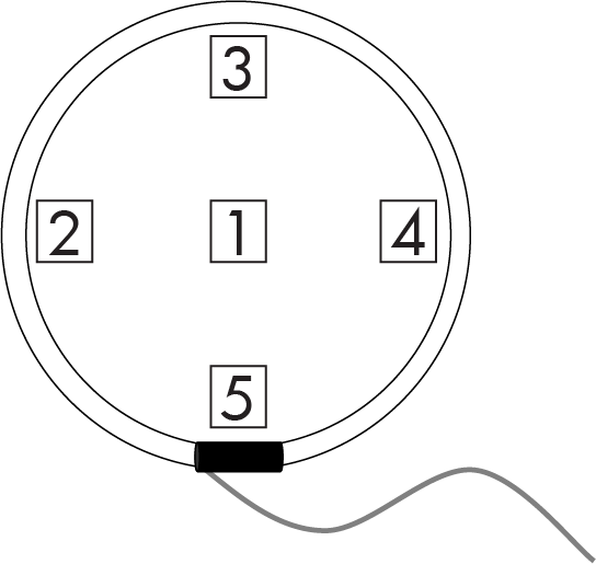
# Rope CT Positioning Guide
Rope CTs should be installed properly to reduce the maximum error based on positioning. Ideally the conductor being monitored will be perpendicular to the rope CT loop, and pass through the center of the rope CT as shown below in position 1. Tie-wraps or other non-conductive fasteners can be used to center the rope CT around the conductor. The percentages listed below are the expected maximum errors that will be introduced in addition to the base rope accuracy.
[](https://kb.egauge.net/uploads/images/gallery/2020-12/rope-positions.png)
| **Position Number** | **Position Description** | **Error** |
| 1 | Centered | < 0.4% |
| 2, 3, 4 | Near outer edge | < 2.0% |
| 5 | Near connector | < 4.0% |
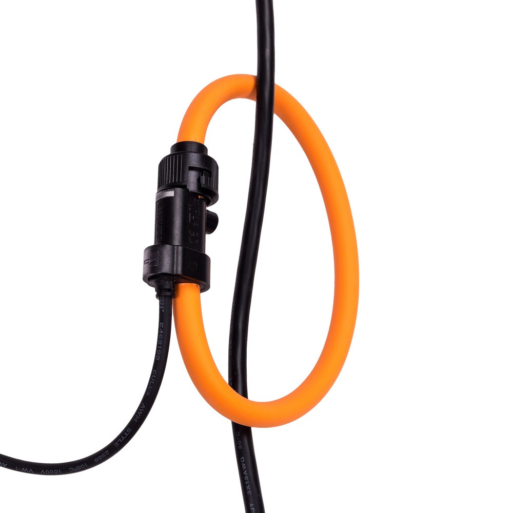
| [](https://kb.egauge.net/uploads/images/gallery/2020-12/position-good.jpg)
*Conductor through center of rope CT (ideal placement)*
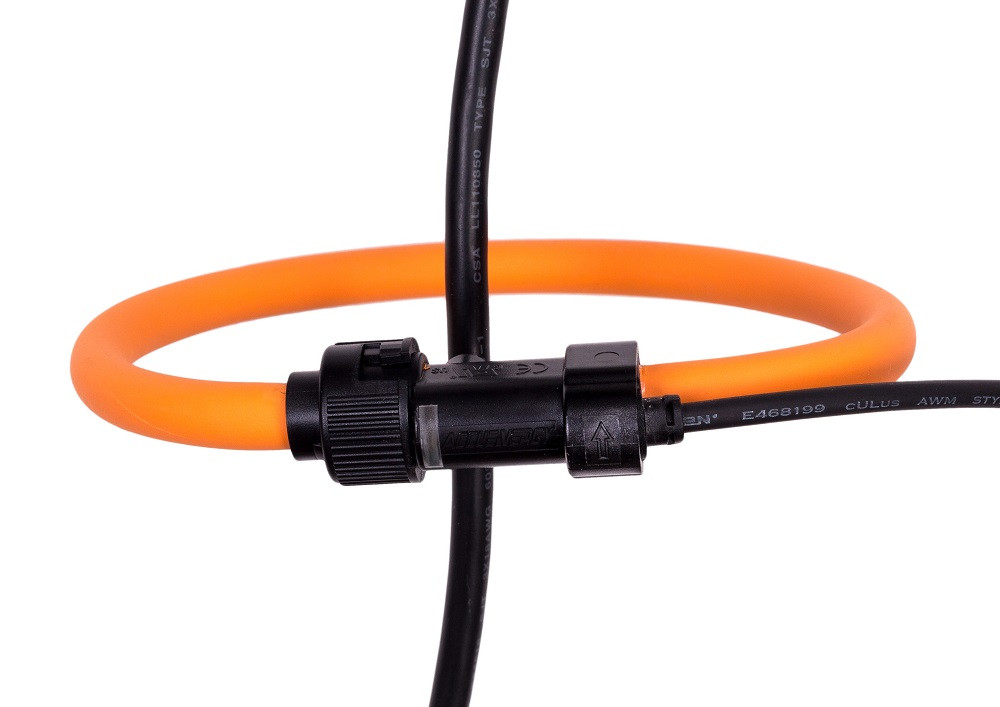
| [](https://kb.egauge.net/uploads/images/gallery/2020-12/position-touching-edges.jpg)
*Conductor touching points 4 and 2 (less than ideal placement)*
|